COLOUR VIDEO MONITOR INSTRUCTIONS TM-2100PN-K – + B Y/ C A VIDEO VIDEO ON OFF TM-2100PN-K PHASE CHROMA BRIGHT CONTRAST MENU VOLUME/SELECT INPUT SELECT POWER LCT0054-002A-H LCT0054-002A-H 1 02.07.
Thank you for purchasing this JVC colour video monitor. Before using it, read and follow all instructions carefully to take full advantage of the monitor’s capabilities. SAFETY PRECAUTIONS In order to prevent any fatal accidents caused by misoperation or mishandling the monitor, be fully aware of all the following precautions. WARNINGS To prevent fire or shock hazard, do not expose this monitor to rain or moisture. Dangerous high voltages are present inside the unit.
POWER CONNECTION WARNING Do not cut off the main plug from this equipment. If the plug fitted is not suitable for the power points in your home or the cable is too short to reach a power point, then obtain an appropriate safety approved extension lead or adapter or consult your dealer. The wire which is coloured green-and-yellow must be connected to the terminal which is marked with the letter E or the safety earth symbol ˙ or coloured green or green-and-yellow.
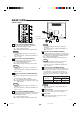
CONTROLS AND FEATURES FRONT VIEW 1 3 2 5 7 4 9 6 8 11 10 15 – TM-2100PN-K – + B Y/ C PHASE CHROMA BRIGHT CONTRAST MENU B + Y/ C A VIDEO VIDEO ON OFF INPUT SELECT VOLUME/SELECT POWER A VIDEO VIDEO ON OFF TM-2100PN-K PHASE CHROMA BRIGHT CONTRAST MENU VOLUME/SELECT INPUT SELECT POWER 12 13 14 1 Phase button [PHASE ] Press this button to set the picture hue adjustment mode. Adjust the value with the VOLUME/SELECT buttons.
REAR VIEW A IN OUT 16 IN OUT 17 VIDEO B IN A Y/ C 18 IN OUT IN OUT VIDEO B IN Y/ C OUT OUT A IN OUT B IN OUT REMOTE IN OUT AUDIO A IN OUT 19 B IN OUT 20 REMOTE IN OUT 21 AUDIO To AC outlet (230 V AC, 50 Hz/60 Hz) 16 Video A terminals [VIDEO A IN/OUT] Video signal input (IN) and output (OUT) terminals. The output terminal is bridge-connected.
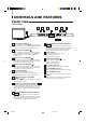
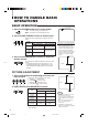
HOW TO HANDLE BASIC OPERATIONS BASIC OPERATION Colour system indication (PAL or NTSC) 1. Press the POWER switch to turn on the power. _ON : Power turns ON. (Power indicator: lit) —OFF : Power turns OFF. (Power indicator: unlit) ON OFF PAL POWER 2. Press the INPUT SELECT button to choose input. Y/ C Selects video/audio signals input to terminals on the rear panel.
HOW TO USE THE MENU FUNCTIONS DISPLAY AND SELECTION IN THE
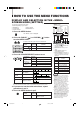
HOW TO USE THE MENU FUNCTIONS (cont’d) DISPLAY AND SELECTIONS IN THE MODE (SETTING) screen You can set the following set-up menu items. ● H. POSITION ● V. POSITION ● WHITE BALANCE ● CONTROL LOCK ● B.P.S. LEVEL ● REMOTE SELECT 1 ‰ H. POSITION : 00 V. POSITION : 00 WHITE BALANCE CONTROL LOCK : OFF B. P. S. LEVEL : 10 REMOTE SELECT : OFF Notes: ● Parameters for H. POSITION and V.
Set-up menu items Purpose H. POSITION V.
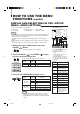
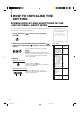
HOW TO INITIALISE THE SETTING SCREEN DISPLAY AND SELECTIONS IN THE RESET MODE You can set
BASIC CONNECTION EXAMPLE Notes: * Before connecting your system, make sure that all units are turned off. * The illustration below shows some examples of different connections. Terminal connections may differ depending on the component connected. Be sure to refer to the instructions provided with the unit(s) you are connecting. * Each pair of input (IN) and output (OUT) terminals are bridge-connected.
BASIC CONNECTION EXAMPLE (cont’d) 7 VIDEO B (VIDEO) Connection Example (Select Input B (VIDEO) button) A Video Camera IN OUT IN OUT Video Video (Video signal cable) (Video signal cable) VIDEO B VCR IN Y/ C OUT Video Monitor A IN OUT B IN OUT REMOTE IN OUT Audio AUDIO Audio (Audio signal cable) Video Monitor (Audio signal cable) VCR External control switch REMOTE open circuit (open) RCA pin REMOTE (Remote cable) (Remote cable) short circuit (short) – + B Y/ C A VIDEO V
TROUBLESHOOTING Solutions to common problems related to your monitor are described here. If none of the solutions presented here solves the problem, unplug the monitor and consult a JVC-authorised dealer or service centre for assistance. Problems Points to be checked Measures (Remedy) No power supply. Is the power plug loosened or disconnected? Firmly insert the power plug. No picture with the power on. Is the video signal output from the connected component? Set the connected component correctly.
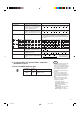
SPECIFICATIONS MODEL TM-2100PN-K Type Colour video monitor Colour system PAL, NTSC (3.58) Picture tube 54 cm measured diagonally, flat-square type, 90° deflection, in-line gun, vertical line trio type (phosphor stripe pitch 0.69 mm) Effective screen size Width Height Diagonal 406.4 mm 304.8 mm 508 mm Scanning frequency H : 15.734 kHz (NTSC), 15.625 kHz (PAL) V : 59.
7 Dimensions Unit : mm < Side View > < Front View > 1.3 476 479 9.5 407.5 314.8* 50.2 416.4* – + B Y/ C A VIDEO VIDEO ON OFF TM-2100PN-K PHASE CHROMA BRIGHT CONTRAST MENU VOLUME/SELECT INPUT SELECT POWER 3.5 382.8 105 135 128.5 492 * Asterisks (∗) are used to indicate front panel dimensions. 7 Y/C (Mini DIN 4 pin) terminal specification 2 4 1 3 Pin No. IN 2 4 Y/C OUT 1 3 Signal 1 GND (Y) 2 GND (C) 3 Y 4 C 15 LCT0054-002A-H 15 02.07.
TM-2100PN-K COLOUR VIDEO MONITOR VICTOR COMPANY OF JAPAN, LIMITED Printed in Thailand 0702-Y-U-JMT © 2002 VICTOR COMPANY OF JAPAN, LIMITED LCT0054-002A-H 16 02.07.