BEDIENUNGSANLEITUNG : FARB-VIDEO-MONITOR MANUEL D’INSTRUCTIONS : MONITEUR VIDEO COULEUR MANUALE DI ISTRUZIONI : MONITOR VIDEO A COLORI INSTRUCCIONES : MONITOR DE VIDEO A COLOR DEUTSCH INSTRUCTIONS FRANÇAIS TM-A210G ENGLISH COLOR VIDEO MONITOR ITALIANO For Customer Use: Enter below the Serial No. which is located on the rear of the cabinet. Retain this information for future reference. Pour l’usage du client: Enter ci-dessous le numéro de série qui est situé sur l’arrière du coffret.
INSTRUCTIONS TM-A210G Thank you for purchasing this JVC color video monitor. Before using it, read and follow all instructions carefully to take full advantage of the monitor’s capabilities. EN_TM_A210GE.p65 1 03.3.
SAFETY PRECAUTIONS In order to prevent any fatal accidents caused by misoperation or mishandling the monitor, be fully aware of all the following precautions. WARNINGS To prevent fire or shock hazard, do not expose this monitor to rain or moisture. Dangerous high voltages are present inside the unit. Do not remove the back cover of the cabinet. When servicing the monitor, consult qualified service personnel. Never try to service it yourself. WARNING : THIS APPARATUS MUST BE EARTHED.
POWER CONNECTION The power supply voltage rating of this product is 120 V AC (For U.S.A. and Canada only) and 220 – 240 V AC (For European countries or United Kingdom), the power cord attached conforms to the following power supply voltage and countries. Use only the power cord designated to ensure Safety and EMC regulations of each countries. Power cord Power supply voltage : 120 V AC Countries : U.S.A.
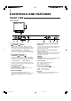
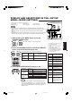
CONTROLS AND FEATURES FRONT VIEW 1 Chroma/Phase button [ CHROMA/ 5 Input A (VIDEO) button and lamp [INPUT SELECT A] PHASE] Press this button to activate the picture color density adjustment mode or picture hue adjustment mode. Each time you press the button, the adjustment item changes. Picture color density Ô Picture hue Adjust the value with the VOLUME/SELECT buttons 3. Also used as a control button in the menu function mode.
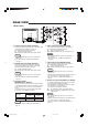
REAR VIEW Input (IN) and output (OUT) terminals for the audio signal corresponding to the VIDEO A terminals e. The output terminal is bridge-connected. IN : Audio signal input terminal OUT : Bridge-connected audio signal output terminal Notes: ÷ For corresponding video signals, use the VIDEO A terminal e. ÷ Also refer to BASIC CONNECTION EXAMPLE on page 12.
CONTROLS AND FEATURES REAR VIEW To AC outlet (120 V AC, 50 Hz/60 Hz) For U.S.A. and Canada To AC outlet (220 – 240 V AC, 50 Hz/60 Hz) For Europe For the United Kingdom y AC inlet [AC IN] Power input connector. Connect the provided AC power cord u to an AC outlet (120 V AC or 220 – 240 V AC, 50 Hz/60 Hz). u Power cord Connects the provided power cord (120 V AC or 220 – 240 V AC, 50 Hz/60 Hz) to the AC IN connector y.
HOW TO HANDLE BASIC OPERATIONS BASIC OPERATION STATUS indication (PAL or NTSC) 1. Press the POWER switch to turn on the power. _ ON : Power turns ON. (Power indicator: lit) — OFF : Power turns OFF. (Power indicator: unlit) PAL 2. Press the INPUT SELECT buttons to choose input. Select video/audio signals input to terminals on the rear panel. The lamp for the selected button lights up.
HOW TO USE THE MENU FUNCTIONS DISPLAY AND SELECTION IN THE
DISPLAY AND SELECTIONS IN THE MODE (SETTING) screen You can set the following set-up menu items. • H. POSITION • WHITE BALANCE • CONTROL LOCK • STATUS DISPLAY • INPUT REMOTE • ASPECT REMOTE Notes: ÷ Parameter for H. POSITION can be set separately depending on the video input (Input A (VIDEO) or Input B (VIDEO)) selected by the input select buttons on the front panel. Select the required video input with the input select buttons on the front panel in advance.
HOW TO USE THE MENU FUNCTIONS (cont’d) Set-up menu items Purpose H. POSITION WHITE BALANCE DRIVE CUT OFF Settings Adjusts the horizontal position of the screen (+ : Horizontal position shifts to the right/–: Horizontal position shifts to the left) –05 –04 –01 00 +04 +05 Adjusts the white balance Selects DRIVE (DRV) or CUT OFF (CUTO) adjustment. Screen setting is changed to the selected setting mode. R.DRIVE Adjusts red level –09 –08 –01 00 +01 +08 +09 B.
HOW TO INITIALIZE THE SETTING SCREEN DISPLAY AND SELECTIONS IN THE RESET MODE You can set
BASIC CONNECTION EXAMPLE Notes: • Before connecting your system, make sure that all units are turned off. • The illustration below shows some examples of different connections. Terminal connections may differ depending on the component connected. Be sure to refer to the instructions provided with the unit(s) you are connecting. • Each pair of input (IN) and output (OUT) terminals are bridge-connected.
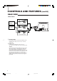
7 VIDEO B (Y/C) Connection Example (Select Input B (Y/C)) Audio Audio (Audio signal cable) (Audio signal cable) Video Camera VCR Y/C (S-video) (Y/C (S-video) signal cable) Video Monitor Video Monitor Y/C (S-video) VCR ENGLISH (Y/C (S-video) signal cable) : Signal Flow 13 EN_TM_A210GE.p65 13 03.3.
TROUBLESHOOTING Solutions to common problems related to your monitor are described here. If none of the solutions presented here solves the problem, unplug the monitor and consult a JVC-authorized dealer or service center for assistance. Problems Points to be checked Measures (Remedy) No power supply. Is the power plug loosened or disconnected? Firmly insert the power plug. No picture with the power on. Is the video signal output from the connected component? Set the connected component correctly.
SPECIFICATIONS MODEL TM-A210G Type Color video monitor Colour system PAL, NTSC (3.58) Picture tube 54 cm measured diagonally, flat-square type, 90° deflection, in-line gun, vertical line trio type (phosphor stripe pitch H/V: 0.63/0.64 mm) Width Height Diagonal 406.4 mm (16") 304.8 mm (12") 508 mm (20") Scanning frequency H: 15.734 kHz (NTSC), 15.625 kHz (PAL) V: 59.
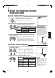
7 Dimensions Unit : mm (inch) < Side View > < Front View > 476 (18-3/4) 479 (18-7/8) 416.4 (16-1/2) * CHROMA CONTRAST PHASE BRIGHT VOLUME/SELECT 213.5 (8-1/2) 314.8 (12-1/2) * A MENU 407.5 (16-1/8) 1.5 (1/16) B 3 (1/8) ON OFF INPUT SELECT POWER 382.8 (15-1/8) 3.5 (1/4) 105 (4-1/4) 20 ( 7/8) 135 (5-3/8) 128.5 (5-1/8) 492 (19-3/8) * Asterisks (*) are used to indicate front panel dimensions. 7 Y/C (Mini DIN 4 pin) terminal specification Pin No.