VF-HP840U_EN.book Page 1 Thursday, January 17, 2008 2:48 PM VIEWFINDER VF-HP840U INSTRUCTIONS Thank you for purchasing this JVC product. Before beginning to operate this unit, please read the instructions carefully to ensure the best possible performance. For Customer Use: Enter below the Serial No. which is located on the body. Retain this information for future reference. Model No. Serial No.
VF-HP840U_EN.book Page 2 Thursday, January 17, 2008 2:48 PM Getting Started FOR USA These are general IMPORTANT SAFEGUARDS and certain items may not apply to all appliances. IMPORTANT SAFEGUARDS 1. 2. 3. 4. Read all of these instructions. Save these instructions for later use. All warnings on the product and in the operating instructions should be adhered to. Unplug this appliance system from the wall outlet before cleaning. Do not use liquid cleaners or aerosol cleaners. Use a damp cloth for cleaning.
VF-HP840U_EN.book Page 3 Thursday, January 17, 2008 2:48 PM Safety Precautions INFORMATION (FOR CANADA) RENSEIGNEMENT (POUR CANADA) This Class A digital apparatus complies with Canadian ICES-003. FOR USA AND CANADA Cet appareil num rique de la Classe A est conforme á la norme NMB-003 du Canada. CAUTION RISK OF ELECTRIC SHOCK DO NOT OPEN CAUTION: TO REDUCE THE RISK OF ELECTRIC SHOCK. DO NOT REMOVE COVER (OR BACK). NO USER-SERVICEABLE PARTSINSIDE. REFER SERVICING TO QUALIFIED SERVICE PERSONNEL.
VF-HP840U_EN.book Page 4 Thursday, January 17, 2008 2:48 PM Getting Started Safety Precautions (continued) Information for Users on Disposal of Old Equipment [European Union] FOR EUROPE This equipment is in conformity with the provisions and protection requirements of the corresponding European Directives.
VF-HP840U_EN.book Page 5 Thursday, January 17, 2008 2:48 PM Table of Contents Features This product is an 8.4-inch color viewfinder for use in the GYHD250U/KA-HD250U studio system. Getting Started Safety Precautions . . . . . . . . . . . . . . . . . . . . . . . . . . Table of Contents . . . . . . . . . . . . . . . . . . . . . . . . . . . Features . . . . . . . . . . . . . . . . . . . . . . . . . . . . . . . . . . Precautions During Use . . . . . . . . . . . . . . . . . . . . . .
VF-HP840U_EN.book Page 6 Thursday, January 17, 2008 2:48 PM Getting Started Precautions During Use Location of Storage and Use Energy Conservation 䢇 Do not place this product at the following locations. When this product is not used for a prolonged period of time, turn off the power of the system for safety and energy conservation purposes. Doing so may cause the product to malfunction or break down. ● Hot or cold places beyond the allowable operating temperature range of 0°C to +40°C.
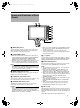
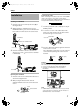
VF-HP840U_EN.book Page 7 Thursday, January 17, 2008 2:48 PM Names and Functions of Parts (Front) H H MENU A B STATUS C CONTRAST D 4 PEAKING 5 6 4 5 6 BRIGHT 1:1 FOCUS ASSIST E F G H A [MENU] Dial (Button) Scroll up and down this dial to move up and down the cursor (X) for selecting items when the Menu screen is displayed. Press the dial to confirm the selected item.
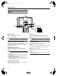
VF-HP840U_EN.book Page 8 Thursday, January 17, 2008 2:48 PM Getting Started Names and Functions of Parts (Rear) M N DC INPUT RETURN VR CABLE J TALLY I ON OFF K O L I [TALLY] Switch M TALLY Lamp This turns ON/OFF the TALLY lamp M. ON : TALLY is enabled. OFF : TALLY is disabled. This displays the monitor status of the input screen in red. Only when Tally PGM (Program) signals are input, the lamp lights up in red.
VF-HP840U_EN.book Page 9 Thursday, January 17, 2008 2:48 PM Setup Installation Connecting VF cable When connecting the VF cable, be sure to turn off the POWER switch on the camera or on the remote control unit first. Connect the viewfinder [VF CABLE] terminal to the KA-HD250U VF output terminal with the provided VF cable. Mounting on KA-HD250U 1 2 Rotate the lock level as shown by the arrow ( ) in the diagram below.
VF-HP840U_EN.book Page 10 Thursday, January 17, 2008 2:48 PM Setup Installation (continued) Outputting images 1 Mounting hood cover (provided) 1 2 Align the hood cover with the groove on top of the viewfinder screen and insert from the top. Secure with the screw found under the center of the viewfinder screen. When setting the POWER switch on remote control or camera to AONB, image will be output on the viewfinder.
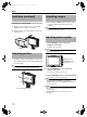
VF-HP840U_EN.book Page 11 Thursday, January 17, 2008 2:48 PM Menu Menu Setting Method Entering camera name 1 MENU STATUS Display the [OTHERS] menu screen. - - [MENU] dial [MENU] button - ON HP 8 4 0 U CO L OR C A NC E L 4 PEAKING 5 6 4 5 6 BRIGHT CONTRAST OTHERS C AME RA N AME N AME E D I T B L A C K &WH I T E ME NU R E S E T P AGE B A C K 1:1 FOCUS ASSIST 1 Press the [MENU] button for 1 second or more during normal screen display. 2 The [MAIN MENU] screen appears.
VF-HP840U_EN.book Page 12 Thursday, January 17, 2008 2:48 PM Menu Menu screen content The Menu screen consists of the following structure as shown below. - - M A I N M E NU - - MA R K ER S E T T I NG . . S HOO T I NG A S S I S T . . V I D EO F ORMA T . . OTHERS . .
VF-HP840U_EN.book Page 13 Thursday, January 17, 2008 2:48 PM MARKER SETTING Menu Screen Settings in bold are factory default settings. Item Setting Value ASPECT TYPE VIDEO CINEMA Description This item sets the purpose of the marker. VIDEO : Aspect for TV broadcast shooting CINEMA : Aspect for cinema shooting Note: ● When the input format is 4:3, ACINEMAB cannot be selected.( [VIDEO] is displayed.
VF-HP840U_EN.book Page 14 Thursday, January 17, 2008 2:48 PM Menu Menu screen content (continued) SHOOTING ASSIST Menu Screen Settings in bold are factory default settings. Item Setting Value FOCUS ASSIST RED GREEN BLUE Description This item sets the display color of the focus section when the FOCUS ASSIST function is operated. RED : Displays the focus section in red. GREEN : Displays the focus section in green. BLUE : Displays the focus section in blue.
VF-HP840U_EN.book Page 15 Thursday, January 17, 2008 2:48 PM VIDEO FORMAT Menu Screen Settings in bold are factory default settings. Item Setting Value INPUT SIGNAL COMPONENT RGB AUTO Description Select the input signal method of the [VF CABLE] terminal. COMPONENT: Inputs YPbPr signals. RGB : Inputs RGB signals. (FORMAT is fixed at [480I] or [576I].) AUTO : Automatically recognizes input signals. When the screen is not output normally with Auto Recognition, set to other setting.
VF-HP840U_EN.
VF-HP840U_EN.book Page 17 Thursday, January 17, 2008 2:48 PM Setting Selection DIP Switch You can switch the setting (factory setting) for certain functions. All DIP switches are set to "OFF" in the factory settings. Method of opening Remove the two screws fastening the cover on the bottom of this product and open the cover. 䡵 DIP Switch 1 Setting for the power supply function Function Setting to ON/OFF the backlight function when the power is supplied from the [DC INPUT].
VF-HP840U_EN.book Page 18 Thursday, January 17, 2008 2:48 PM Others 䡵 Accessories Specifications 䡵 General Connected Target Equipment : KA-HD250U Power Supply : 12 V DC (11 V DC to 18 V DC) Power Consumption : Approx. 13 W and below Ambient Temperature : 0 °C to 40 °C Allowable Operating Humidity : 30 % RH to 80 % RH Mass : 1.6 kg (excluding hood) 1.
VF-HP840U_EN.book Page 19 Thursday, January 17, 2008 2:48 PM 130 Dimensional Outline Drawing (Unit: mm) With Hood 195 184 261 Without Hood 90 12 67 MENU 261 4 PEAKING 5 6 4 CONTRAST 5 6 4 BRIGHT 5 6 STATUS 1:1 FOCUS ASSIST The specifications and appearance of this product and other related products may be modified for improvement without prior notice.
VF-HP840U_EN.