FIXED IP DOME CAMERA ITALIANO VN-C215V4U START-UP GUIDE ESPAÑOL FRANÇAIS DEUTSCH ENGLISH VN-C215_EN.book Page 1 Tuesday, March 20, 2007 1:54 PM For Customer Use: Enter below the Serial No. which is located on the body. Retain this information for future reference. VN-C215V4U Model No. Serial No. Thank you for purchasing this JVC product. Before beginning to operate this unit, please read the instructions carefully to ensure the best possible performance.
VN-C215_EN.book Page 2 Tuesday, March 20, 2007 1:54 PM Introduction Safety Precautions FOR USA These are general IMPORTANT SAFEGUARDS and certain items may not apply to all appliances. IMPORTANT SAFEGUARDS 1. 2. 3. 4. Read all of these instructions. Save these instructions for later use. All warnings on the product and in the operating instructions should be adhered to. Unplug this appliance system from the wall outlet before cleaning. Do not use liquid cleaners or aerosol cleaners.
FOR USA AND CANADA CAUTION RISK OF ELECTRIC SHOCK DO NOT OPEN CAUTION : TO REDUCE THE RISK OF ELECTRIC SHOCK. DO NOT REMOVE COVER (OR BACK). NO USER-SERVICEABLE PARTSINSIDE.REFER SERVICING TO QUALIFIED SERVICE PERSONNEL. The lightning flash wish arrowhead symbol, within an equilateral triangle is intended to alert the user to the presence of uninsulated "dangerous voltage" within the product's enclosure that may be of sufficient magnitude to constitute a risk of electric shock to persons.
VN-C215_EN.book Page 4 Tuesday, March 20, 2007 1:54 PM Introduction Safety Precautions (continued) Information for Users on Disposal of Old Equipment [European Union] This symbol indicates that the electrical and electronic equipment should not be disposed as general household waste at its end-of-life.
● This installation should be made by a qualified service person and should conform to all local codes. ● This installation shall be in accordance with the National Electrical Code, ANSI/NFPA 70. ● The unit is to be powered by an DC 12 V power supply. ● The DC 12 V power supply should conform to the following: Class 2 only (For USA), Isolated power supply only (For Europe and other).
VN-C215_EN.book Page 6 Tuesday, March 20, 2007 1:54 PM Introduction Main Features 䡵 High Picture Quality The camera unit of VN-C215V4U employs a 380,000-pixel CCD (1/4") which enables high quality image monitoring. 䡵 Wide shooting range 䡵 Built-in Viewer Monitoring via a computer is possible by downloading the built-in viewer onto the computer. 䡵 HTTP-based API VN-C215V4U comes with a HTTP-based API. This feature enables setting and control via the network.
Contents Introduction Safety Precautions ............................. 2 Main Features ..................................... 6 Contents ............................................. 7 Operating Environment ....................... 8 Cautionary Notes ................................ 8 Name and Function of Parts ............. 10 Features ........................................... 14 Setup Overall Procedures ........................... 16 Mounting the Camera ....................... 16 Before Mounting ........
VN-C215_EN.book Page 8 Tuesday, March 20, 2007 1:54 PM Introduction Operating Environment 䡵 PC Specification Requirements OS : Windows XP (Professional or Home Edition) (SP2) CPU : Pentium4 1.5 GHz (or higher) Memory : 1 GB and above Hard disk space : Free space of 20 MB and above Video card : 1024 ⳯ 768 pixels or higher, True Color (24 or 32 bits) Web browser : Internet Explorer Version 6.0 䡵 LAN Environment ● 10BASE-T/100BASE-TX network interconnected using an IEEE802.3compliant switching hub.
Others Copyrights of video 䢇 This product has a built-in AGC circuit. When AGC is AOnB, the product sensitivity increases automatically at dark places and the image on the screen may appear grainy. This is not a malfunction. 䢇 When White Balance is set to AAutoB, the principle of automatic tracking white balance circuit may cause the color of the image to be different from the actual color of the object, depending on the condition of the object. However, this is not a malfunction.
VN-C215_EN.book Page 10 Tuesday, March 20, 2007 1:54 PM Introduction Name and Function of Parts Camera unit I H B A A B G C D E A Mounting hole (elliptical) ⳯ 4 Use these when mounting the camera to the electrical box. (A Pg. 22) B Mounting hole (round) ⳯ 4 Use these when mounting the camera to the ceiling or wall. (A Pg. 20, 22) C Outer case Use this in the following cases: ● When mounting the camera directly to the ceiling or on the wall. (A Pg.
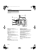
ENGLISH VN-C215_EN.book Page 11 Tuesday, March 20, 2007 1:54 PM Camera unit/Inside the camera T This is when the dome cover, inner cover and outer case is removed. How to remove ( A Pg. 17 AMounting on a ceilingB Steps 3. to 5.) Lens section (A Pg. 13) W J K V U T Behind the camera unit P Y MAC address S R L X Q P M N O H Power supply/Alarm signal cable (A Pg.
VN-C215_EN.book Page 12 Tuesday, March 20, 2007 1:54 PM Introduction Name and Function of Parts (continued) Inside the camera Lens section (A Pg. 13) W J K L M N Q Ceiling Mount Bracket (x3) This serves as a bracket when embedding the camera in a ceiling. (A Pg. 17) R Camera Fastening Screw This secures the camera unit N and the outer case C. How to remove (A Pg. 18, 20) S Pan fastening screw Make sure you loosen the screw before setting.
ENGLISH VN-C215_EN.book Page 13 Tuesday, March 20, 2007 1:54 PM Lens section SPOT Z FOCUS ADJ IRIS ADJ b c FOR SERVICE a L IRIS LEVEL H Z [FOCUS ADJ] Focus adjustment button This is used to adjust the lens focus. Press the button to open the lens Iris for 30 seconds. The focus is now easier to adjust as the depth of field becomes shallow. (A Pg. 29) Memo : ● Pressing the focus adjustment button automatically activates the electronic shutter. The screen may flicker but this is not a malfunction.
VN-C215_EN.book Page 14 Tuesday, March 20, 2007 1:54 PM Introduction Features Saving JPEG images to the FTP server at regular intervals JPEG images may be uploaded to the FTP server at regular intervals. Monitoring Via Built-in Viewer VN-C215V4U comes with a built-in ActiveX viewer. Monitoring of VN-C215V4U images using the computer is possible by installing this built-in viewer on the computer. Images that are currently displayed may also be captured in the computer’s hard disk.
ENGLISH VN-C215_EN.book Page 15 Tuesday, March 20, 2007 1:54 PM Restrictions on Clients It is possible for VN-C215V4U to permit or deny image acquisition of designated IP addresses. Control via customized application software The following uses are also possible by developing a customized application software that supports the API of VN-C215V4U. For details, please refer to the [API Guide] in the attached CD-ROM. ● Monitoring via the computer while at the same time recording images to the HDD.
VN-C215_EN.book Page 16 Tuesday, March 20, 2007 1:54 PM Setup Overall Procedures The connection and setup procedures are described as below. 䢇 Make sure you touch the metal surface of the [MONITOR] terminal to release the static electricity from your body. Static electricity may cause the camera to malfunction. Step 1 Setup (A Pg. 16) Mount the camera and configure image settings. K Step 2 Network Settings (A Pg. 30) Configure the network settings of the computer and this camera.
Selecting Mounting Method The procedures differ according to the mounting method. Check the respective items before mounting. Mounting on a ceiling T The thickness of the ceiling material should be between 9.5 mm and 22 mm. Note : 䡵 Setup ● To mount the camera using an electrical box, please check with your dealer or nearest JVC servicing center. 1. Open a hole in the ceiling (R120 mm,4-3/4 Mounting Method 䢇 Mounting on a ceiling (A Pg. 17) 䢇 Mounting directly on a ceiling or alongside a wall (A Pg.
VN-C215_EN.book Page 18 Tuesday, March 20, 2007 1:54 PM Setup Mounting the Camera (continued) Mounting on a ceiling (continued) 4. Remove the inner dome. The inner dome is secured by 3 clips. Remove the inner dome from the clips. 5. Remove the outer case. (The outer case is not used for this mounting method.) A Loosen the camera fastening screws with a screwdriver. B Turn the camera in the anti-clockwise direction and remove the outer case. 6. Remove the fall-prevention wire.
䡵 Mounting 䡵 Image adjustment 1. Face the imaging direction mark (j) in the When the camera is mounted, adjust the image settings while looking at the actual image. (A Pg.27 AImage adjustmentB) shooting direction and mount the camera. 2. Secure the camera in 3 locations. A Use a cross slot screw driver to push the screw head of the ceiling mounting bracket right in. B While holding onto the screwdriver, turn it approximately 90 degrees in the clockwise direction.
VN-C215_EN.book Page 20 Tuesday, March 20, 2007 1:54 PM Setup 5. Remove the outer case. Mounting the Camera (continued) A Loosen the camera fastening screws with a screwdriver. B Turn the camera in the anti-clockwise direction and remove the outer case. Mounting the camera directly on a ceiling or alongside a wall To mount on a wall, use the same procedures below but replace the word “ceiling” with “wall”. 䡵 Setup 1.
䡵 Mounting Outer case mounting screw Less than 3 mm Towards fastening hook 1 2 From the ceiling slab 1. Align the secured outer case with the position alignment mark of the camera. Note : ● Make sure that the cables are not caught in the outer case. 2. Turn the camera in the clockwise direction. T Check that the ○ mark can be seen. (Refer to the diagram below) 3. Tighten the Camera Fastening Screws and secure the camera.
VN-C215_EN.book Page 22 Tuesday, March 20, 2007 1:54 PM Setup Mounting the Camera (continued) Mounting the camera to the electrical box Note : Mount by allowing the cable to exit from the side You can also mount the camera on a ceiling or wall by pulling the cables horizontally instead of drilling a hole. The basic mounting method is the same as eMounting the camera directly on a ceiling or alongside a wallf (A Pg. 20). 1.
VN-C215_EN.book Page 23 Tuesday, March 20, 2007 1:54 PM ENGLISH 䡵 Mounting Attach the camera to the outer case that has been fastened to the electrical box. 1. Follow steps 2. to 6. of AMount by allowing the cable to exit from the sideB [Connection] (A Pg. 20) 䡵 Image Adjustment After mounting is completed, adjust the images while checking the actual image. (A Pg.
VN-C215_EN.book Page 24 Tuesday, March 20, 2007 1:54 PM Setup Power Connection Electricity can be supplied to this product either by using the PoE or connecting to the DC12 V power supply. 䢇 When electricity is supplied to the camera, the status indicator blinks, and turns off when startup is complete. Note : Using the PoE Connect to a device that supports PoE and supply electricity from the LAN cable.
Connecting to the DC12 V power supply Connect this product to the DC12 V power supply when not using the PoE. Connect the polarity correctly. Red : DC12V+ Black : DC12V- Warning The rated power of this product is DC12 V. Make sure to use it with the correct voltage. Supplying a power different from the rated value may result in failures and in the worst scenario, smoking and fire. Note : Memo : ● Make sure to select only one mode of electrical supply.
VN-C215_EN.book Page 26 Tuesday, March 20, 2007 1:54 PM Setup LAN Cable Connection Connect the camera to a hub or computer using a LAN cable. 䡵 When connecting to a hub Alarm Input/Output Cable Connection Connect the alarm input/output cables with external devices such as a sensor, buzzer, etc. Make use of a straight cable. Signal name 䡵 When connecting to a computer Make use of a Cross Over cable.
Image adjustment Alarm Input Connect this terminal to sensor devices, such as an infrared sensor, door sensor, metal sensor, manual switch, etc. When the camera is mounted, adjust the image settings while looking at the actual image. 䡵 Input requirements Mounting the test monitor ● No-voltage relay NPN open collector input ● Polarity of input detection can be selected using a software ● Make/Break (500 ms and above) ● Circuit current at low level: 0.3 mA ● Applied voltage at high level: 3.
VN-C215_EN.book Page 28 Tuesday, March 20, 2007 1:54 PM Setup Memo : Image adjustment (continued) Adjusting the camera shooting direction This camera can be adjusted for pan, tilt and rotation. Adjust the direction and face the camera towards the object. Note : ● Make sure you touch the metal surface of the [MONITOR] terminal to release the static electricity in your body before adjusting the camera shooting direction.
Field angle adjustment Loosen the fastening screw of the zoom adjustment ring, move the ring horizontally and adjust the image size. Focus adjustment Press the focus adjustment button. The Iris will open for approximately 30 seconds. Loosen the fastening screw of the focus adjustment ring, move the ring horizontally and adjust the focus. Memo : ● Repeat EField angle adjustmentF and EFocus adjustmentF 2 to 3 times and configure the settings.
VN-C215_EN.book Page 30 Tuesday, March 20, 2007 1:54 PM Setting Network Requirements Insufficient network bandwidth ● Ensure that there is sufficient network bandwidth for the data volume to be sent out by VN-C215V4U. ● Data volume to be sent by VN-C215V4U varies with the settings and number of distributions. ● The maximum bit rate from VN-C215V4U is about 9 Mbps. When there is insufficient bandwidth, the number of JPEG frames (frame rate) that the client can acquire will decrease.
IP Address Settings Setting IP address with the default VNC215V4U settings There are 2 methods to set the IP address when VN-C215V4U is in its default settings. (A) Assigning an IP address to VN-C215V4U from the DHCP server (B) Assigning a static IP address to VNC215V4U 䡵 (A) Assigning an IP address from the DHCP server ● VN-C215V4U is set to ADHCP EnableB (the DHCP client function is ON) by default.
VN-C215_EN.book Page 32 Tuesday, March 20, 2007 1:54 PM Setting IP Address Settings (continued) 䢇 IP Address setting at the computer Set the computer to an IP address that enables communication with VN-C215V4U. 1. Click [Start] ● Select in the order of [Control Panel]-[Network Connection]-[Local Area]. 2. The computer with which Internet Explorer is launched automatically selects the connected network ● Right-click and select [Properties].
䢇 Changing the IP address using the Internet Explorer 1. Launch the Internet Explorer on the computer 2. When proxy setting is enabled in the Internet Explorer, follow the steps below to disable the proxy of the Internet Explorer ● Select in the order of [Tools]-[Internet Options...]-[Connections]-[LAN Setting], followed by deselecting the check for [Use a proxy server for your LAN] in [Proxy Server] of the [Local Area Network(LAN)Settings] window. Deselect the check 3.
VN-C215_EN.book Page 34 Tuesday, March 20, 2007 1:54 PM Setting IP Address Settings (continued) 䢇 Changing the IP address using the Internet Explorer (continued) 4. Launch the Internet Explorer A Enter the following IP address in the address field. http://192.168.0.2 B Click [Go]. Memo : ● If the proxy server setting in Internet Explorer is enabled, you may not be able to specify the IP address directly. In this case, change the proxy settings of the Internet Explorer.
VN-C215_EN.book Page 35 Tuesday, March 20, 2007 1:54 PM ENGLISH 6. The top page of VN-C215V4U appears Click on [Network], followed by [Basic] on the next submenu. 7. The Basic page with the IP address settings appears A Set the [IP Setting] item to [DHCP Disable]. B Enter the values you wish to specify in [IP Address], [Subnet Mask] and [Default Gateway]. C Click [OK]. A confirmation screen appears. Press the [OK] button. The VN-C215V4U restarts using the new IP address.
VN-C215_EN.book Page 36 Tuesday, March 20, 2007 1:54 PM Setting IP Address Settings (continued) When the IP address of VN-C215V4U is known When the IP address of VN-C215V4U is known, it can be changed by using Internet Explorer on the computer to access the built-in web page of VN-C215V4U. T Please refer to the ASetting Using Internet ExplorerB of the [INSTRUCTIONS] (pdf) in the supplied CD-ROM.
VN-C215_EN.book Page 37 Tuesday, March 20, 2007 1:54 PM ENGLISH Operation Operation of Built-in Viewer Using the built-in viewer enables display of a series of images, one-shot recording of images and receiving of alarm information. ⽧Setting Up the Internet Explorer (A Pg. 38) ⽧Installing the built-in viewer (A Pg. 40) ⽧Screen Configuration of Built-in Viewer (A Pg. 41) ⽧Quitting the Built-in Viewer (A Pg. 42) ⽧Shortcut for Built-in Viewer (A Pg.
VN-C215_EN.book Page 38 Tuesday, March 20, 2007 1:54 PM Operation Operation of Built-in Viewer (continued) Setting Up the Internet Explorer 1. Launch the Internet Explorer on the computer 2. When proxy setting is enabled in the Internet Explorer, follow the steps below to disable the proxy of the Internet Explorer ● Select in the order of [Tools]-[Internet Options...
3. If Active X controls and plug-ins of the Internet Explorer is disabled, follow the steps below to enable it ● Click [Trusted sites] under [Tools]-[Internet Options...]-[Security]. Upon doing so, the [Sites...] button directly below becomes active. Click on this button and deselect the check for [Require server verification(https:) for all sites in this zone] in the displayed window. Next, add the IP address of VN-C215V4U. If the setting is factory default, add the following web site to the zone.
VN-C215_EN.book Page 40 Tuesday, March 20, 2007 1:54 PM Operation Operation of Built-in Viewer (continued) Installing the built-in viewer 1. Enter the URL of the built-in viewer in the address field of Internet Explorer For example, if the IP address of VN-C215V4U is 192.168.0.2, enter as follows: http://192.168.0.2/cgi-bin/c215viewing.cgi A Enter the URL of the built-in viewer of this camera. (The default URL is http://192.168.0.2/cgi-bin/ c215viewing.cgi) BSelect [Go] http://192.168.0.
ENGLISH VN-C215_EN.book Page 41 Tuesday, March 20, 2007 1:54 PM Screen Configuration of Built-in Viewer ● VN-C215V4U is set to encode at 15 fps by default. A B C D E A Alarm Appears blinking when alarm packets are sent from VN-C215V4U to the computer. The alarm will continue blinking until the auto clear operation of the alarm is performed. Clicking the blinking button turns the light off. B Display Size Switches the display size.( VGA or QVGA) C Pause Pauses/Resumes playback of images.
VN-C215_EN.book Page 42 Tuesday, March 20, 2007 1:54 PM Operation Operation of Built-in Viewer (continued) Quitting the Built-in Viewer To quit, press the [Close] button at the top right of the window. Click [Close]. ● To restart the built-in viewer, launch the Internet Explorer and enter the URL of the built-in viewer in the address field. For example, if the IP address of VN-C215V4U is 192.168.0.2, enter as follows: http://192.168.0.2/cgi-bin/c215viewing.
ENGLISH VN-C215_EN.book Page 43 Tuesday, March 20, 2007 1:54 PM Shortcut for Built-in Viewer Creating a shortcut for the built-in viewer on the Desktop screen of the computer saves you the trouble of having to enter the URL in the Internet Explorer. Create the shortcut using the procedures below. 1. Launch the Internet Explorer 2.
VN-C215_EN.book Page 44 Tuesday, March 20, 2007 1:54 PM Others Specifications General Alarm Input : No-voltage a contact input, NPN open collector input, low level, latch/momentary (500 ms and above) (Circuit current during low level: 0.3 mA; Applied voltage during high level: 3.3 V) Alarm Output : NPN open collector output (Allowable applied voltage: 12 V; Allowable inflow current: 50 mA) Camera Unit Image pickup device : 1/4 inch Interline transfer CCD Effective pixels : Approx.
ENGLISH VN-C215_EN.book Page 45 Tuesday, March 20, 2007 1:54 PM Dimension [Unit: mm(inches)] ⽧When embedded ⽧When cover is attached Ǿ116 (4-9/16) 89 (3-1/2) 46 (1-13/16) ) /8 -1 (2 83,5 (3-5/16) 89 (3-1/2) 55 SR 71 (2-13/16) 55 (2-3/16) 58 (2-5/16) 4-Ǿ4,5 (3/16) 4,5 (3/16) 6 (1/4) Ǿ145 (5-3/4) 55 SR 133 (5-1/4) Ǿ120 (4-3/4) ) /8 -1 (2 Ǿ145 (5-3/4) T Specifications and appearance of this unit and related products are subject to change for product improvement without prior notice.
DEUTSCH VN-C215_GE.book Page 1 Tuesday, March 20, 2007 2:20 PM FIXED IP DOME CAMERA VN-C215V4U SCHNELLEINSTIEG Danke, dass Sie sich für den Kauf dieses Produktes von JVC entschieden haben. Bitte lesen Sie diese Anleitung sorgfältig durch, bevor Sie das Gerät in Betrieb nehmen, denn nur so können Sie seine Leistungsmerkmale optimal nutzen.
VN-C215_GE.book Page 2 Tuesday, March 20, 2007 2:20 PM Einleitung Sicherheitshinweise ACHTUNG: UM DER GEFAHR VON BRÄNDEN UND ELEKTRISCHEN SCHLÄGEN VORZUBEUGEN, DARF DIESES GERÄT WEDER DEM REGEN NOCH HOHER FEUCHTIGKEIT AUSGESETZT WERDEN. ACHTUNG Um elektrische Schläge zu vermeiden, das Gehäuse nie öffnen. Im Innern befinden sich keine Teile, die vom Benutzer gewartet werden können. Überlassen Sie die Wartung qualifiziertem Service-Personal.
● Installations- und Montagearbeiten sind von qualifiziertem Fachpersonal entsprechend den geltenden Richtlinien durchzuführen. ● Installations- und Montagearbeiten sind in Übereinstimmung mit dem National Electrical Code, ANSI/NFPA 70, durchzuführen (nur in den USA anwendbar). ● Dieses Gerät ist mit einem 12-VGleichstromnetzteil zu betreiben. ● Das 12-V-Gleichstromnetzteil muss folgenden Anforderungen genügen: Nur Klasse 2 (nur in den USA anwendbar).
VN-C215_GE.book Page 4 Tuesday, March 20, 2007 2:20 PM Einleitung Wichtigste Leistungsmerkmale 䡵 Hohe Bildqualität Die Kameraeinheit der VN-C215V4U basiert auf einem 1/4"-CCD mit 380.000 Bildpunkten und gewährleistet so eine hohe Bildqualität. 䡵 Großer Erfassungsbereich Die Kamera bietet einen großen Einstellbereich für den zu erfassenden Bereich und ist mithilfe eines Drehjustiermechanismus auch zur Wandmontage geeignet.
VN-C215_GE.book Page 5 Tuesday, March 20, 2007 2:20 PM Einleitung Sicherheitshinweise ............................ 2 Wichtigste Leistungsmerkmale ........... 4 Inhaltsverzeichnis ............................... 5 Betriebsbedingungen .......................... 6 Warnhinweise ..................................... 6 Bedienelemente und Funktionen ........ 8 Merkmale .......................................... 12 Einrichtung Gesamtablauf ................................... 14 Montage der Kamera ................
VN-C215_GE.book Page 6 Tuesday, March 20, 2007 2:20 PM Einleitung Betriebsbedingungen 䡵 PC-Anforderungen Betriebssystem : Windows XP Home Edition/ XP Professional einschl. SP2 CPU : Pentium 4, 1,5 GHz (oder besser) Speicher : > 1 GB Festplattenspeicher: mind. 20 Mbyte freier Speicherplatz Grafikkarte : 1024 ⳯ 768 Bildpunkte (min.), True Color (24- oder 32-Bit-Farben) Webbrowser : Internet Explorer Version 6.
Sonstiges Urheberrechtliche Hinweise 䢇 Diese Kamera hat eine integrierte AGC-Schaltung. Wenn AGC die Einstellung COnD hat, erhöht sich die Empfindlichkeit an dunklen Orten automatisch, wodurch das Bild auf dem Bildschirm körnig wirken kann. Dies ist keine Fehlfunktion. 䢇 Wenn White Balance die Einstellung CAutoD hat, können sich je nach Objektbedingungen die Bildfarben von den tatsächlichen Objektfarben unterscheiden. Es handelt sich dabei um eine Folge der Betriebsweise der Weißabgleichslogik.
VN-C215_GE.book Page 8 Tuesday, March 20, 2007 2:20 PM Einleitung Bedienelemente und Funktionen Kameraeinheit I H B A A B G C D E A Montageöffnung (oval) ⳯ 4 Verwenden Sie diese Öffnungen zur Montage an der Anschlussdose. (A S. 20) B Montageöffnung (rund) ⳯ 4 Verwenden Sie diese Öffnungen zur Wandbzw. Deckenmontage. (A S. 18, 20) C Außengehäuse Dieses verwenden Sie in den folgenden Fällen: ● zur direkten Montage der Kamera an Wand oder Decke (A S. 18) ● zur Montage an einer Anschlussdose (A S.
VN-C215_GE.book Page 9 Tuesday, March 20, 2007 2:20 PM Kameraeinheit (innen) DEUTSCH T Nachfolgende Abbildung zeigt das Gerät nach Entfernen von Kuppelabdeckung, innerer Abdeckung und Außengehäuse. Hinweise zum Entfernen dieser Komponenten finden Sie unter A S. 15 CDeckenmontageD, Schritte 3. bis 5. W Objektivbereich (A S. 11) J K V U T Rückseite der Kameraeinheit P Y MAC address S R L X Q P M N O H Stromversorgung/Alarmkabel (A S.
VN-C215_GE.book Page 10 Tuesday, March 20, 2007 2:20 PM Einleitung Bedienelemente und Funktionen (fortsetzung) Kamerainneres Objektivbereich (A S. 11) W J K L M N Q Deckenmontagehalterung (× 3) Diese Halterung wird bei der Deckenmontage der Kamera verwendet. (A S. 15) R Befestigungsschraube für die Kamera Mit dieser Schraube befestigen Sie die Kameraeinheit N am Außengehäuse C. Hinweise zum Entfernen unter (A S.
VN-C215_GE.book Page 11 Tuesday, March 20, 2007 2:20 PM SPOT Z FOCUS ADJ IRIS ADJ DEUTSCH Objektivbereich b c FOR SERVICE a L IRIS LEVEL H Z [FOCUS ADJ]-Einstelltaste (Scharfstellung) Erinnerung: Mit dieser Taste stellen Sie die Scharfstellung ein. Betätigen Sie die Taste, um die Objektivblende für 30 Sekunden zu öffnen. Dies erleichtert die Scharfstellung, da die Feldtiefe verringert wird. (A S.
VN-C215_GE.book Page 12 Tuesday, March 20, 2007 2:20 PM Einleitung Merkmale Speichern von JPEG-Bildern auf dem FTP-Server in regelmäßigen Abständen Überwachung mit dem integrierten Viewer Die VN-C215V4U wird mit einem integrierten ActiveX-Viewer ausgeliefert. Die Anzeige von VN-C215V4U-Bildern mithilfe eines Computers ist nach Installation dieses integrierten Viewers auf dem Computer möglich. Angezeigte Bilder können auch auf der Festplatte des Computers abgelegt werden.
VN-C215_GE.book Page 13 Tuesday, March 20, 2007 2:20 PM Beschränkungen auf Clients DEUTSCH Die VN-C215V4U ist in der Lage, die Bildaufzeichnung abhängig von der angegebenen IP-Adresse zu gestatten oder abzulehnen. Steuerung über angepasste Anwendungssoftware Es sind ferner die folgenden Einsatzmöglichkeiten möglich, wofür allerdings die Entwicklung einer angepassten Anwendungssoftware erforderlich ist, die die Anwendungsschnittstelle (API) der VN-C215V4U unterstützen muss.
VN-C215_GE.book Page 14 Tuesday, March 20, 2007 2:20 PM Einrichtung Gesamtablauf Herstellen der Anschlussverbindungen und Einrichten des Systems sind nachfolgend beschrieben. 䢇 Stellen Sie sicher, dass Sie die Metalloberfläche des [MONITOR]Anschlusses berühren, um sich zu erden (d. h. die statische Elektrizität Ihres Körpers abzuleiten). Andernfalls kann eine solche statische Aufladung zu Fehlfunktionen der Kamera führen. Schritt 1 Konfiguration (A S.
VN-C215_GE.book Page 15 Tuesday, March 20, 2007 2:20 PM Die Vorgehensweise unterscheidet sich je nach gewählter Montagemethode. Überprüfen Sie die jeweiligen Komponenten vor Beginn der Montage. Anmerkung: ● Wenn Sie die Kamera mithilfe einer Anschlussdose montieren wollen, wenden Sie sich an Ihren Händler oder das für Sie zuständige JVC-Kundendienstzentrum. Montagemethode 䢇 Deckenmontage (A S. 15) 䢇 Direktaufbau auf die Decke oder eine Seitenwand (A S.
VN-C215_GE.book Page 16 Tuesday, March 20, 2007 2:20 PM Einrichtung 䡵 Verbindungen Montage der Kamera (fortsetzung) Deckenmontage (fortsetzung) 4. Entfernen Sie die innere Kuppel. Die innere Kuppel ist mit drei Bügeln befestigt. Lösen Sie die innere Kuppel von den Bügeln. 5. Entfernen Sie das Außengehäuse. (Das Außengehäuse wird für diese Montagemethode nicht verwendet.) A Lösen Sie die Befestigungsschrauben der Kamera mit einem Schraubdreher.
䡵 Montage 䡵 Bildjustierung 1. Richten Sie die Richtungsmarkierung (j) Wenn die Kamera montiert ist, justieren Sie unter Beobachtung des aufgezeichneten Bildes die Bildeinstellungen. (A S.25 CBildjustierungD) in die Aufnahmerichtung aus und befestigen Sie dann die Kamera. 2. Die Kamera muss an drei Stellen befestigt werden. A Drücken Sie mit einem Kreuzschlitzschraubdreher den Schraubenkopf der Deckenmontagehalterung ein. B Drehen Sie den weiterhin aufgesetzten Schraubdreher um 90° im Uhrzeigersinn.
VN-C215_GE.book Page 18 Tuesday, March 20, 2007 2:20 PM Einrichtung Montage der Kamera (fortsetzung) B Drehen Sie die Kamera nun gegen den Uhrzeigersinn und entfernen Sie das Außengehäuse. C Lösen Sie das Sicherheitskabel vom Befestigungshaken Direktaufbau der Kamera auf die Decke oder eine Seitenwand 6. Lösen Sie die Schwenkfeststellschraube. Wenn Sie die Kamera an eine Wand montieren, ersetzen Sie in der nachfolgenden Beschreibung den Ausdruck „Decke“ durch „Wand“.
VN-C215_GE.book Page 19 Tuesday, March 20, 2007 2:20 PM 䡵 Montage Montageschraube des Außengehäuses 1. Richten Sie das befestigte Außengehäuse auf die Markierung der Kamera aus. ● Achten Sie darauf, dass sich die Kabel nicht im Außengehäuse verfangen. Zum Befestigung shaken 1 2 2. Drehen Sie die Kamera im Uhrzeigersinn. T Vergewissern Sie sich, dass das Zeichen Åõ sichtbar ist. (Siehe nachfolgende Abbildung.) 3. Ziehen Sie die Kamerabefestigungsschrauben an und befestigen Sie so die Kamera.
VN-C215_GE.book Page 20 Tuesday, March 20, 2007 2:20 PM Einrichtung Montage der Kamera (fortsetzung) Montage der Kamera an einer Anschlussdose Anmerkung: Montage mit seitlichem Kabelaustritt Sie können die Kamera auch an einer Decke oder Seitenwand befestigen, indem Sie die Kabel horizontal herausziehen, statt ein Loch zu bohren. Die Vorgehensweise zur Montage ist grundsätzlich identisch mit der unter eDirektaufbau der Kamera auf die Decke oder eine Seitenwandf (A S. 18) beschriebenen Methode. 1.
VN-C215_GE.book Page 21 Tuesday, March 20, 2007 2:20 PM 䡵 Montage DEUTSCH Montieren Sie die Kamera am Außengehäuse, nachdem Sie dieses an der Anschlussdose befestigt haben. 1. Führen Sie die Schritte 2. bis 6. des Abschnitts CMontage mit seitlichem KabelaustrittD [Verbindungen] (A S. 18) durch 䡵 Bildjustierung Wenn die Montage abgeschlossen ist, müssen Sie die Bildjustierung mit optischer Kontrolle vornehmen. (A S.
VN-C215_GE.book Page 22 Tuesday, March 20, 2007 2:20 PM Einrichtung Stromversorgung Die Betriebsspannung kann an dieses Produkt wahlweise über PoE oder durch Anschluss an das 12-V-Gleichstromnetzteil angelegt werden. 䢇 Sobald eine Spannungsquelle mit der Kamera verbunden wird, blinkt die Statusanzeige. Nach Abschluss der Initialisierung erlischt die Anzeige. Anmerkung: ● Wählen Sie in jedem Fall nur eine Art der Spannungsversorgung.
Anschluss an 12-V-Gleichstromnetzteil Warnung Wenn Sie PoE nicht verwenden, schließen Sie dieses Produkt an das 12-V-Gleichstromnetzteil an. Achten Sie beim Anschluss auf korrekte Polarität. Die Nennspannung dieses Produkts beträgt 12 V. Achten Sie auf korrekte Spannungswerte. Das Anlegen einer vom Nennwert abweichenden Spannung kann zu Ausfällen führen. Unter ungünstigsten Bedingungen besteht Rauchentwicklungs- und Feuergefahr.
VN-C215_GE.book Page 24 Tuesday, March 20, 2007 2:20 PM Einrichtung Anschließen des LANKabels Schließen Sie die Kamera über ein LAN-Kabel an einen Hub oder einen Computer an. 䡵 Beim Anschluss an einen Hub Anschließen von Alarmeingangs- und Alarmausgangskabeln Verbinden Sie die Alarmeingangs- und Alarmausgangskabel mit externen Geräten wie einem Sensor, einem Summer usw. Verwenden Sie ein Straight-Through-Kabel. 䡵 Beim Anschluss an einen Computer Verwenden Sie ein Crossover-Kabel.
VN-C215_GE.book Page 25 Tuesday, March 20, 2007 2:20 PM Anmerkung: Verbinden Sie diesen Eingang mit Sensorgeräten wie Infrarotsensoren, Türsensoren, Metallsensoren, Handschalter o. ä 䡵 Eingangsspezifikation Bildjustierung ● Spannungsfreier Relais- oder NPN-OpenCollector-Eingang ● Die Polarität der Eingangssignalerkennung kann softwareseitig eingestellt werden ● Öffner/Schließer (mind.
VN-C215_GE.book Page 26 Tuesday, March 20, 2007 2:20 PM Einrichtung Bildjustierung (fortsetzung) Kamera ausrichten Bei dieser Kamera lassen sich Schwenkung, Neigung und Rotation einstellen. Stellen Sie die Richtung ein und richten Sie die Kamera auf das Zielobjekt aus. Anmerkung: ● Stellen Sie vor Ausrichtung der Kamera sicher, dass Sie die Metalloberfläche des [MONITOR]-Anschlusses berühren, um sich zu erden (d. h. die statische Elektrizität Ihres Körpers abzuleiten).
VN-C215_GE.book Page 27 Tuesday, March 20, 2007 2:20 PM Lösen Sie die Befestigungsschraube des Zoomrings und justieren Sie das Bild, indem Sie den Ring waagrecht drehen. Fokuseinstellung Betätigen Sie die Fokuseinstelltaste. Die Blende wird nun für ca. 30 Sekunden geöffnet. Lösen Sie die Befestigungsschraube des Fokusrings und justieren Sie das Bild, indem Sie den Ring waagrecht drehen.
VN-C215_GE.book Page 28 Tuesday, March 20, 2007 2:20 PM Einstellungen Netzwerkspezifikation Unzureichende Netzwerkbandbreite ● Stellen Sie sicher, dass genügend Netzwerkbandbreite vorhanden ist, um die von der VN-C215V4U gesendete Datenmenge zu übertragen. ● Die von der VN-C215V4U gesendete Datenmenge variiert in Abhängigkeit von den Einstellungen und der Anzahl der Übertragungen. ● Die maximale Bitrate der VN-C215V4U liegt bei ca. 9 Mbit/s.
VN-C215_GE.book Page 29 Tuesday, March 20, 2007 2:20 PM Einstellen der IP-Adresse mit den Standardeinstellungen der VN-C215V4U Wenn die Standardeinstellungen der VNC215V4U nicht geändert wurden, gibt es zwei Möglichkeiten, die IP-Adresse einzustellen.
VN-C215_GE.book Page 30 Tuesday, March 20, 2007 2:20 PM Einstellungen IP-Adresseinstellungen (fortsetzung) 䢇 IP-Adresseinstellung am Computer Legen Sie für den Computer eine IP-Adresse fest, die die Kommunikation mit der VN-C215V4U gestattet. 1. Klicken Sie auf [Start] ● Wählen Sie [Control Panel]-[Network Connection]-[Local Area]. 2.
VN-C215_GE.book Page 31 Tuesday, March 20, 2007 2:20 PM 䢇 Ändern der IP-Adresse mit dem Internet Explorer beschrieben vor, um den Proxy für den Internet Explorer zu deaktivieren ● Wählen Sie [Tools]-[Internet Options...]-[Connections]-[LAN Setting]. Deaktivieren Sie dann das Kontrollkästchen [Use a proxy server for your LAN] im Bereich [Proxy Server] des Fensters [Local Area Network(LAN)Settings]. Deaktivieren Sie das Kontrollkästchen 3.
VN-C215_GE.book Page 32 Tuesday, March 20, 2007 2:20 PM Einstellungen IP-Adresseinstellungen (fortsetzung) 䢇 Ändern der IP-Adresse mit dem Internet Explorer (fortsetzung) 4. Starten Sie den Internet Explorer A Geben Sie die folgende IP-Adresse in das Adressfeld ein. http://192.168.0.2 B Klicken Sie auf [Go]. Erinnerung: ● Wenn die Proxyservereinstellung im Internet Explorer aktiviert ist, können Sie die IP-Adresse unter Umständen nicht direkt angeben.
VN-C215_GE.book Page 33 Tuesday, March 20, 2007 2:20 PM Klicken Sie auf [Network] und dann im nächsten Untermenü auf [Basic]. 7. Die Seite Basic mit den IP-Adresseinstellungen erscheint A Setzen Sie den Parameter [IP Setting] auf [DHCP Disable]. B Geben Sie die gewünschten Werte in die Felder [IP Address], [Subnet Mask] und [Default Gateway] ein. C Klicken Sie auf [OK]. Ein Bestätigungsfenster erscheint. Klicken Sie auf die Schaltfläche [OK].
VN-C215_GE.book Page 34 Tuesday, March 20, 2007 2:20 PM Einstellungen IP-Adresseinstellungen (fortsetzung) Wenn die IP-Adresse der VN-C215V4U bekannt ist Wenn die IP-Adresse der VN-C215V4U bekannt ist, kann sie mithilfe des Internet Explorer auf dem Computer geändert werden, um die integrierte Webseite der VN-C215V4U aufzurufen. T Weitere Informationen entnehmen Sie dem Abschnitt CSetting Using Internet ExplorerD im Dokument [EINLEITUNG], welches im PDF-Format auf der beiliegenden CD-ROM enthalten ist.
VN-C215_GE.book Page 35 Tuesday, March 20, 2007 2:20 PM Betrieb Betrieb des integrierten Viewers DEUTSCH Der integrierte Viewer gestattet die Anzeige einer Folge von Bildern, die Einmalaufzeichnung von Bildern und den Empfang von Alarmdaten. ⽧Einrichten des Internet Explorer (A S. 36) ⽧Installieren des integrierten Viewers (A S. 38) ⽧Bildschirmkonfiguration des integrierten Viewers (A S. 39) ⽧Beenden des integrierten Viewers (A S. 40) ⽧Verknüpfung zum integrierten Viewer (A S.
VN-C215_GE.book Page 36 Tuesday, March 20, 2007 2:20 PM Betrieb Betrieb des integrierten Viewers (fortsetzung) Einrichten des Internet Explorer 1. Starten Sie den Internet Explorer auf dem Computer 2. Wenn die Proxyeinstellung im Internet Explorer aktiviert ist, gehen Sie wie nachfolgend beschrieben vor, um den Proxy für den Internet Explorer zu deaktivieren ● Wählen Sie [Tools]-[Internet Options...]-[Connections]-[LAN Setting].
3. Wenn Active X controls and plug-ins im Internet Explorer deaktiviert ist, gehen Sie wie folgt vor, um es zu aktivieren ● Klicken Sie auf [Trusted sites] unter [Tools]-[Internet Options...]-[Security]. Daraufhin wird die direkt unterhalb gelegene Schaltfläche [Sites...] verfügbar. Klicken Sie auf diese Schaltfläche und deaktivieren Sie das Kontrollkästchen [Require server verification(https:) for all sites in this zone] im angezeigten Fenster. Fügen Sie nun die IP-Adresse der VN-C215V4U hinzu.
VN-C215_GE.book Page 38 Tuesday, March 20, 2007 2:20 PM Betrieb Betrieb des integrierten Viewers (fortsetzung) Installieren des integrierten Viewers 1. Geben Sie die URL des integrierten Viewers in das Adressfeld des Internet Explorer ein Wenn etwa die IP-Adresse der VN-C215V4U 192.168.0.2 lautet, geben Sie Folgendes ein: http://192.168.0.2/cgi-bin/c215viewing.cgi A Geben Sie die URL des integrierten Viewers dieser Kamera ein. (Die Standard-URL lautet „http://192.168.0.2/cgi-bin/ c215viewing.cgi“.
VN-C215_GE.book Page 39 Tuesday, March 20, 2007 2:20 PM Bildschirmkonfiguration des integrierten Viewers DEUTSCH ● Standardmäßig kodiert die VN-C215V4U mit einer Rate von 15 fps. A B C D E A Alarm Blinkt, wenn Alarmpakete von der VN-C215V4U an den Computer gesendet werden. Die Schaltfläche blinkt fortlaufend, bis die automatische Alarmabschaltfunktion ausgeführt wird. Ebenfalls abgeschaltet wird das Blinken durch Anklicken der Schaltfläche.
VN-C215_GE.book Page 40 Tuesday, March 20, 2007 2:20 PM Betrieb Betrieb des integrierten Viewers (fortsetzung) Beenden des integrierten Viewers Um den Viewer zu beenden, klicken Sie auf die Schließenschaltfläche oben rechts im Fenster. Klicken Sie auf die Schließenschaltfläche. ● Um den integrierten Viewer neu zu starten, starten Sie den Internet Explorer und geben die URL des integrierten Viewers in das Adressfeld ein. Wenn etwa die IP-Adresse der VN-C215V4U 192.168.0.
VN-C215_GE.book Page 41 Tuesday, March 20, 2007 2:20 PM Verknüpfung zum integrierten Viewer DEUTSCH Das Erstellen einer Verknüpfung zum integrierten Viewer auf dem Desktop des Computers erspart Ihnen die Eingabe der URL in den Internet Explorer. Erstellen Sie die Verknüpfung wie nachfolgend beschrieben. 1. Starten Sie den Internet Explorer 2. Klicken Sie mit der rechten Maustaste auf dem Bildschirm auf Internet Explorer und wählen Sie [Create Shortcut] Klicken Sie im Bestätigungsdialogfeld auf [OK].
VN-C215_GE.book Page 42 Tuesday, March 20, 2007 2:20 PM Sonstiges Technische Daten Allgemein Alarmeingang : Spannungsfreier Kontakt, NPN-Open-CollectorEingang, Nullpegel, Latch/ Momentausgabe (>500 ms). (Arbeitsstrom bei Niederpegel: 0,3 mA. Bei Hochpegel angelegte Spannung: 3,3 V). Alarmausgang : NPN-Open-CollectorAusgang (Zulässige Eingangsspannung: 12 V. Zulässiger Eingangsstrom: 50 mA). Kameraeinheit Bilderfassungseinrichtung: 1/4"-Interline-Transfer-CCD Bildpunkte (effektiv) : ca. 380.
VN-C215_GE.book Page 43 Tuesday, March 20, 2007 2:20 PM Abmessungen [Einheit: mm (Zoll)] ⽧Bei versenktem Einbau ⽧Bei montierter Abdeckung ) /8 -1 (2 83,5 (3-5/16) 89 (3-1/2) 55 SR 71 (2-13/16) 55 (2-3/16) 58 (2-5/16) 4-Ǿ4,5 (3/16) Ǿ145 (5-3/4) 55 SR 133 (5-1/4) Ǿ120 (4-3/4) ) /8 -1 (2 Ǿ145 (5-3/4) T Technische Daten und das Erscheinungsbild des Geräts und zugehöriger Produkte können im Sinne einer stetigen Produktverbesserung ohne vorherige Ankündigung geändert werden.
FRANÇAIS VN-C215_FR.book Page 1 Tuesday, March 20, 2007 2:14 PM FIXED IP DOME CAMERA VN-C215V4U MANUEL DE DÉMARRAGE Merci d'avoir acheté ce produit JVC. Avant de commencer à l'utiliser, veuillez lire les instructions attentivement pour garantir les meilleures performances possibles.
VN-C215_FR.book Page 2 Tuesday, March 20, 2007 2:14 PM Introduction Consignes de sécurité ATTENTION Pour éviter les chocs électriques, ne pas ouvrir le coffret. Aucune pièce à l’intérieur n’est à régler par l’utilisateur. Confier les opérations d’entretien au personnel de service qualifié. Cher client, Cet appareil est conforme aux directives et normes européennes en vigueur relatives à la compatibilité électromagnétique et à la protection électrique.
VN-C215_FR.book Page 3 Tuesday, March 20, 2007 2:14 PM Ce manuel décrit l’utilisation élémentaire de VN-C215V4U. Pour les instructions d’utilisation détaillées de VN-C215V4U, consulter AINSTRUCTIONSB. Consulter le fichier AReadmeB sur le CDROM pour les dernières informations. ● Le CD-ROM inclus [INSTRUCTIONS] (pdf), [API Guide] (pdf) et [Search Tool]. ● Pour afficher le fichier en format pdf, AAdobe ReaderB doit être installé sur l’ordinateur.
VN-C215_FR.book Page 4 Tuesday, March 20, 2007 2:14 PM Introduction Fonctions principales 䡵 Fonction de détection de mouvement La caméra de VN-C215V4U emploie un CCD de 380.000 pixels (1/4") qui permet une qualité d’image supérieure. Cette fonction active une alarme en cas de détection de mouvement dans l’image à l’intérieur d’une zone prédéfinie. Les fichiers d’images pré-enregistrés/postenregistrés peuvent être envoyés par FTP à l’aide de l’entrée d’alarme.
VN-C215_FR.book Page 5 Tuesday, March 20, 2007 2:14 PM Introduction Consignes de sécurité ........................ 2 Fonctions principales .......................... 4 Contenu .............................................. 5 Environnement opérationnel ............... 6 Consignes de sécurité ........................ 6 Nom et fonction des pièces ................ 8 Caractéristiques ................................ 12 Configuration Procédures générales ...................... 14 Montage de la caméra ..........
VN-C215_FR.book Page 6 Tuesday, March 20, 2007 2:14 PM Introduction Environnement opérationnel 䡵 Configuration de l’ordinateur Système d’exploitation CPU Mémoire Espace du disque dur Carte vidéo : Windows XP (Professional ou Home Edition) (SP2) : Pentium 4 1,5 GHz (ou supérieur) : 1 Go et plus : 20 Mo d’espace libre ou plus : 1024 ⳯ 768 pixels ou plus, True Color (24 ou 32 bits) Navigateur Web : Internet Explorer Version 6.
Autres Droits d’auteur de la vidéo 䢇 Cette caméra est dotée d’un circuit intégré AGC. Lorsque AGC est AOnB (allumée), la sensibilité de la caméra augmente automatiquement dans les lieux sombres et l’image à l’écran peut paraître granuleuse. Il ne s’agit pas d’une défectuosité de l’appareil.
VN-C215_FR.book Page 8 Tuesday, March 20, 2007 2:14 PM Introduction Nom et fonction des pièces Caméra I H B A A B G C D E A Trou de montage (elliptique) ⳯ 4 Pour le montage de la caméra sur le coffret électrique. (A p. 20) B Trou de montage (rond) ⳯ 4 Pour le montage de la caméra au plafond ou au mur. (A p. 18, 20) C Boîtier extérieur Le boîtier doit être utilisé dans les conditions suivantes: ● Montage direct de la caméra au plafond ou au mur. (A p.
VN-C215_FR.book Page 9 Tuesday, March 20, 2007 2:14 PM Caméra/Intérieur de la caméra T Cette illustration représente l’intérieur de la caméra, lorsque le dôme protecteur, le boîtier intérieur et extérieur sont enlevés. Procédure de retrait ( A p. 15 AMontage au plafondB étapes 3. à 5.) W J K V U T Arrière de la caméra P Y MAC address S R L FRANÇAIS Objectif (A p. 11) X Q P M N O H Alimentation/câble de l’alarme (A p.
VN-C215_FR.book Page 10 Tuesday, March 20, 2007 2:14 PM Introduction Nom et fonction des pièces (Suite) Intérieur de la caméra Objectif (A p. 11) W J K L M N Q Support de montage au plafond (3) Ces supports doivent être utilisés pour encastrer la caméra dans le plafond. (A p. 15) R Vis de fixation de la caméra Cette vis permet de fixer la caméra N et le boîtier extérieur C. Pour effectuer la dépose (A p. 16, 18) S Vis de fixation panoramique Desserrer cette vis avant de procéder au réglage.
VN-C215_FR.book Page 11 Tuesday, March 20, 2007 2:14 PM Objectif SPOT FOCUS ADJ IRIS ADJ b c FRANÇAIS Z FOR SERVICE a L IRIS LEVEL H Z [FOCUS ADJ] Bouton d’ajustement de l’objectif Ce bouton sert à ajuster l’objectif. Enfoncer ce bouton pour ouvrir l’iris de l’objectif pendant 30 secondes. L’objectif devient plus facile à régler car la profondeur du champ est plus profonde. (A p.
VN-C215_FR.book Page 12 Tuesday, March 20, 2007 2:14 PM Introduction Caractéristiques Sauvegarde des images JPEG sur le serveur FTP à intervalles réguliers Surveillance avec visionneuse intégrée La VN-C215V4U est livrée avec une visionneuse ActiveX intégrée. Il est possible de visualiser les images de la VNC215V4U sur ordinateur en effectuant l’installation de la visionneuse intégrée sur ce dernier. Les images en cours de visionnement peuvent également être conservées sur le disque dur de l’ordinateur.
VN-C215_FR.book Page 13 Tuesday, March 20, 2007 2:14 PM Restrictions aux clients La VN-C215V4U peut autoriser ou refuser l’acquisition d’images aux adresses IP désignées. Contrôle par l’intermédiaire d’une application informatique sur mesure FRANÇAIS Les utilisations suivantes sont également possibles en configurant une application informatique sur mesure compatible avec l’API de la VN-C215V4U. Se reporter au [API Guide] sur le CD-ROM ci-joint pour de plus amples informations.
VN-C215_FR.book Page 14 Tuesday, March 20, 2007 2:14 PM Configuration Procédures générales Les procédures de raccordement et de configuration sont décrites ci-dessous. 䢇 Toucher d’abord la surface métallique de la borne [MONITOR] afin de libérer l’électricité statique du corps. L’électricité statique peut entraîner une défectuosisté de la caméra. 1ère étape Configuration (A p. 14) Installer la caméra et configurer les réglages de l’image. K 2e étape Réglages du réseau (A p.
VN-C215_FR.book Page 15 Tuesday, March 20, 2007 2:14 PM Les procédures diffèrent en fonction de la méthode de montage. Vérifier les points respectifs avant de procéder au montage. Montage au plafond T Le plafond doit avoir une épaisseur située entre 9,5 mm et 22 mm. Remarque: 䡵 Configuration ● Pour le montage de la caméra sur le coffret électrique, consulter le détaillant ou le centre de service JVC le plus proche. 1.
VN-C215_FR.book Page 16 Tuesday, March 20, 2007 2:14 PM Configuration Montage de la caméra (Suite) Montage au plafond (Suite) 4. Retirer le boîtier extérieur. Le dôme intérieur est retenu par 3 attaches. Enlever le dôme intérieur des attaches. 䡵 Connexion 1. Fixer l’attache métallique antichute à la caméra. Cette attache fixe la caméra au plafond. 2. Connecter le câble réseau. (A p. 24) 3. Connecter le câble d’alimentation et le câble d’alarme. (A p. 22, 24) Mémo: 5. Retirer le boîtier extérieur.
VN-C215_FR.book Page 17 Tuesday, March 20, 2007 2:14 PM 䡵 Montage 䡵 Réglage des images 1. Aligner le repère (j) dans le sens de Une fois que la caméra est installée, régler les paramètres de l’image pendant le visionnant de l’image. (A p.25 ARéglage des imagesB) 2. Fixer la caméra aux trois emplacements. A Au moyen d’un tournevis cruciforme, enfoncer la tête de vis du support de montage au plafond. B En tenant le tournevis, le tourner environ à 90 degrés dans le sens horaire.
VN-C215_FR.book Page 18 Tuesday, March 20, 2007 2:14 PM Configuration Montage de la caméra (Suite) 5. Retirer le boîtier extérieur. A Desserrer les vis de fixation de la caméra avec un tournevis. B Tourner la caméra dans le sens antihoraire et Montage de la caméra directement au plafond ou au mur C Retirer l’attache antichute du crochet de Pour monter la caméra au mur, suivre toutes les directives du montage au plafond en remplaçant le mot “plafond” par le mot “mur”. 6.
VN-C215_FR.book Page 19 Tuesday, March 20, 2007 2:14 PM 䡵 Montage Vis de montage du boîtier extérieur 1. Aligner le boîtier extérieur fixé avec le repère d’alignement de la caméra. Remarque: Vers le crochet de fixation 1 2 ● Vérifier que les câbles ne sont pas coincés dans le boîtier extérieur. 2. Tourner la caméra dans le sens horaire. T Vérifier que le repère Åõ soit visible. (Se reporter au diagramme ci-dessous) 3. Serrer les vis de fixation afin de fixer la caméra.
VN-C215_FR.book Page 20 Tuesday, March 20, 2007 2:14 PM Configuration Montage de la caméra (Suite) Installer de manière à ce que le câble sorte par le côté Vous pouvez également faire l’installation de la caméra sur le plafond ou sur le mur en tirant les câbles de côté au lieu de percer un trou. La méthode de montage est sensiblement la même que eMontage de la caméra directement au plafond ou au murf (A p. 18). 1.
VN-C215_FR.book Page 21 Tuesday, March 20, 2007 2:14 PM 䡵 Montage Fixer la caméra au boîtier extérieur qui a été attaché au coffret électrique. 1. Suivre les étapes 2. à 6. du AInstaller de manière à ce que le câble sorte par le côtéB [Connexion] (A p. 18) 䡵 Réglage des images FRANÇAIS Une fois l’installation terminée, régler les paramètres de l’image pendant le visionnement de l’image. (A p.
VN-C215_FR.book Page 22 Tuesday, March 20, 2007 2:14 PM Configuration Alimentation électrique La caméra peut être alimentée en courant soit en utilisant le PoE ou en la branchant avec la prise de courant DC 12 volts. 䢇 Lorsque la caméra est mise sous tension, le témoin clignote puis s’éteint lorsque le démarrage est terminé. Remarque: ● N’utiliser qu’un seul moyen d’alimentation de courant.
VN-C215_FR.book Page 23 Tuesday, March 20, 2007 2:14 PM Connexion à une alimentation électrique DC 12 volts Avertissement Connecter cet appareil à une alimentation électrique DC 12 volts lorque le PoE n’est pas utilisé. Vérifier de respecter les polarités. Rouge : DC12V+ Noir : DC12V- La puissance nominale de cet appareil est DC 12 volts. Vérifier que la tension appropriée est utilisée.
VN-C215_FR.book Page 24 Tuesday, March 20, 2007 2:14 PM Configuration Connexion du câble de réseau local Brancher la caméra à un concentrateur ou un ordinateur utilisant un câble de réseau. 䡵 La connexion à un concentrateur Utiliser un câble direct. 䡵 La connexion à un ordinateur Utiliser un câble simulateur de modem. Connexion du câble de l’entrée et de sortie d’alarme Connecter les câbles de l’entrée et de sortie d’alarme aux périphériques tels que capteur, avertisseur sonore, etc.
VN-C215_FR.book Page 25 Tuesday, March 20, 2007 2:14 PM Remarque: Entrée d’alarme Connecter cette borne aux appareils détecteurs, tels que senseur infrarouge, senseur de porte, détecteur de métal, commutateur manuel, etc. 䡵 Spécifications d’entrée Réglage des images Exemple de senseur (1) DC3.3 V R VCC Entrée 1 ou entrée 2 OUT 3.3 V R Une fois que la caméra est installée, régler les paramètres de l’image pendant le visionnant de l’image.
VN-C215_FR.book Page 26 Tuesday, March 20, 2007 2:14 PM Configuration Réglage des images (Suite) Réglage de l’angle de prise de vue de la caméra Il est possible d’effectuer un réglage panoramique, d’inclinaison et de rotation à cette caméra. Régler l’angle de prise de vue et dirigez la caméra vers l’objet. Remarque: ● Avant de régler l’angle de prise de vue, toucher la surface métallique de la borne [MONITOR] afin de libérer l’électricité statique de votre corps.
VN-C215_FR.book Page 27 Tuesday, March 20, 2007 2:14 PM Desserrer la vis de fixation de la bague de réglage du zoom, tourner la bague pour régler la dimension de l’image. Réglage du foyer Appuyer sur le bouton de réglage du foyer. L’iris s’ouvre pendant environ 30 secondes. Desserrer la vis de fixation de la bague de réglage du foyer, tourner la bague pour le régler. Mémo: ● Répéter de deux à trois fois ERéglage de l’angle de champF et ERéglage du foyerF, puis configurer les réglages.
VN-C215_FR.book Page 28 Tuesday, March 20, 2007 2:14 PM Réglages Spécifications de réseau Largeur de bande réseau insuffisante ● Vérifier que la bande passante du réseau est suffisante pour le volume de données qui sera transmis par VN-C215V4U. ● Le volume des données transmis par VNC215V4U varie en fonction des réglages et du nombre de distributions. ● Le débit binaire maximal du VN-C215V4U est d’environ 9 Mbits.
VN-C215_FR.book Page 29 Tuesday, March 20, 2007 2:14 PM Configuration de l’adresse IP avec les paramètres par défaut du VN-C215V4U Il existe deux méthodes pour configurer l’adresse IP lorsque VN-C215V4U utilise les paramètres par défaut. (A) Assigner une adresse IP au VN-C215V4U par le serveur DHCP (B) Assigner une adresse IP statique à VNC215V4U 䡵 (A) Assigner une adresse IP par le serveur DHCP ● VN-C215V4U est configuré à ADHCP EnableB (la fonction client DHCP est activée) par défaut.
VN-C215_FR.book Page 30 Tuesday, March 20, 2007 2:14 PM Réglages Paramètres de l’adresse IP (Suite) 䢇 Configuration de l’adresse IP sur l’ordinateur Configurer l’ordinateur à une adresse IP qui permet la communication avec VN-C215V4U. 1. Cliquer sur [Start]. ● Sélectionner dans l’ordre suivant [Control Panel]-[Network Connection]-[Local Area]. 2. L’ordinateur qui sert à ouvrir Internet Explorer sélectionne automatiquement le réseau connecté ● Faire un clic droit et sélectionner [Properties].
VN-C215_FR.book Page 31 Tuesday, March 20, 2007 2:14 PM 䢇 Modification de l’adresse IP par Internet Explorer 1. Ouvrir Internet Explorer sur l’ordinateur 2. Lorsque le paramètre du proxy est activé sous Internet Explorer, suivre les étapes ci- FRANÇAIS dessous pour désactiver le proxy de Internet Explorer ● Sélectionner dans l’ordre [Tools]-[Internet Options...
VN-C215_FR.book Page 32 Tuesday, March 20, 2007 2:14 PM Réglages Paramètres de l’adresse IP (Suite) 䢇 Modification de l’adresse IP par Internet Explorer (Suite) 4. Ouvrir Internet Explorer A Inscrire l’adresse IP suivante dans le champ de l’adresse. B Cliquer sur [Go]. http://192.168.0.2 Mémo: ● Il est possible que vous ne puissiez indiquer l’adresse IP directement, si le paramètre du serveur proxy dans Internet Explorer est activé. Dans tel cas, modifier les paramètres du proxy de Internet Explorer.
VN-C215_FR.book Page 33 Tuesday, March 20, 2007 2:14 PM 6. La page du haut du VN-C215V4U apparait FRANÇAIS Cliquer sur [Network], ensuite sur [Basic] du sous-menu suivant. 7. La page Basic avec les paramètres de l’adresse IP apparaît A Sélectionner le point [IP Setting] pour le [DHCP Disable]. B Inscrire les valeurs que vous souhaitez indiquer pour [IP Address], [Subnet Mask] et [Default Gateway]. C Cliquer sur [OK]. Un message de confirmation s’affiche. Appuyer sur le bouton [OK].
VN-C215_FR.book Page 34 Tuesday, March 20, 2007 2:14 PM Réglages Paramètres de l’adresse IP (Suite) Lorsque l’adresse IP du VN-C215V4U est connue Lorsque l’adresse IP du VN-C215V4U est connue, elle peut être modifiée en utilisant Internet Explorer sur l’ordinateur pour accéder la page Web intégrée du VN-C215V4U. T Vous reporter aux [INSTRUCTIONS] (PDF) du ASetting Using Internet ExplorerB fournies avec le CD-ROM.
VN-C215_FR.book Page 35 Tuesday, March 20, 2007 2:14 PM Fonctionnement Fonctionnement de la visionneuse intégrée La visionneuse intégrée affiche une série d’images, un enregistrement d’images et reçoit les informations d’une alarme. FRANÇAIS ⽧Configuration de Internet Explorer (A p. 36) ⽧Installation de la visionneuse intégrée (A p. 38) ⽧Configuration de l’écran de la visionneuse intégrée (A p. 39) ⽧Quitter la visionneuse intégrée (A p. 40) ⽧Raccourci pour la visionneuse intégrée (A p.
VN-C215_FR.book Page 36 Tuesday, March 20, 2007 2:14 PM Fonctionnement Fonctionnement de la visionneuse intégrée (Suite) Configuration de Internet Explorer 1. Ouvrir Internet Explorer sur l’ordinateur 2. Lorsque le paramètre du proxy est activé sous Internet Explorer, suivre les étapes cidessous pour désactiver le proxy de Internet Explorer ● Sélectionner dans l’ordre [Tools]-[Internet Options...
VN-C215_FR.book Page 37 Tuesday, March 20, 2007 2:14 PM 3. Si Active X controls and plug-ins dans Internet Explorer est désactivé, suivre les étapes cidessous pour l’activer ● Sélectionner [Trusted sites] sous [Tools]-[Internet Options...]-[Security]. Dès que le bouton [Sites...], en dessous, est sélectionné, il devient actif. Cliquer sur ce bouton et enlever la coche de la rubrique [Require server verification(https:) for all sites in this zone] dans la fenêtre ouverte.
VN-C215_FR.book Page 38 Tuesday, March 20, 2007 2:14 PM Fonctionnement Fonctionnement de la visionneuse intégrée (Suite) Installation de la visionneuse intégrée 1. Saisir l’adresse URL de la visionneuse intégrée dans le champ de l’adresse de Internet Explorer Par exemple, si l’adresse IP du VN-C215V4U est 192.168.0.2, inscrire comme suit: http://192.168.0.2/cgi-bin/c215viewing.cgi A Saisir l’adresse URL de la visionneuse intégrée de cette caméra. (L’adresse URL par défaut est http://192.168.0.
VN-C215_FR.book Page 39 Tuesday, March 20, 2007 2:14 PM Configuration de l’écran de la visionneuse intégrée FRANÇAIS ● Par défaut, le VN-C215V4U est réglé pour encoder à 15 fps. A B C D E A Alarm Clignote lorsque des données d’alarme sont envoyées du VN-C215V4U à l’ordinateur. L’alarme continuera à clignoter jusqu’à ce que la fonction d’effacement automatique de l’alarme soit exécutée. La lumière s’éteint lorsque vous cliquez sur le bouton clignotant.
VN-C215_FR.book Page 40 Tuesday, March 20, 2007 2:14 PM Fonctionnement Fonctionnement de la visionneuse intégrée (Suite) Quitter la visionneuse intégrée Pour quitter, appuyer le bouton [Close] dans le coin supérieur droit de la fenêtre. Cliquer sur [Close]. ● Pour redémarrer la visionneuse intégrée, ouvrir Internet Explorer et entrer l’adresse URL de la visionneuse intégrée dans le champ d’adresse. Par exemple, si l’adresse IP du VN-C215V4U est 192.168.0.2, inscrire comme suit: http://192.168.0.
VN-C215_FR.book Page 41 Tuesday, March 20, 2007 2:14 PM Raccourci pour la visionneuse intégrée Si vous créez un raccourci pour la visionneuse intégrée sur le bureau de votre ordinateur, vous économiserez du temps en n’ayant pas besoin d’inscrire, chaque fois, l’adresse URL dans Internet Explorer. Suivre les procédures ci-dessous pour créer un raccourci. 1. Ouvrir Internet Explorer FRANÇAIS 2.
VN-C215_FR.book Page 42 Tuesday, March 20, 2007 2:14 PM Autres Spécifications Généralités Entrée d’alarme : Entrée de contact sans tension, entrée collecteur ouvert NPN, bas niveau, verrouillage/temporaire (500 ms et plus) (Courant du circuit à niveau faible: 0,3 mA; Tension appliquée à niveau élevé: 3,3 volts) [Sortie du moniteur] Sortie du moniteur par 1 (75, 1 Vp-p) Résolution : 540 lignes télévision (typ.
VN-C215_FR.book Page 43 Tuesday, March 20, 2007 2:14 PM Dimension (Appareil: mm (pouces) ⽧Une fois encastrée ⽧Avec le dôme protecteur Ǿ116 (4-9/16) 89 (3-1/2) 46 (1-13/16) Ǿ145 (5-3/4) 55 SR 133 (5-1/4) Ǿ120 (4-3/4) ) /8 -1 (2 Ǿ145 (5-3/4) T Les spécifications et l’apparence de cette caméra et des produits connexes sont assujetties à des changements sans préavis aux fins d’amélioration de produit.
VN-C215_SP.book Page 1 Tuesday, March 20, 2007 2:31 PM VN-C215V4U GUÍA DE INICIO Gracias por adquirir este producto de JVC. Antes de utilizar esta unidad, lea las instrucciones atentamente para asegurarse de que obtiene el máximo rendimiento posible.
VN-C215_SP.book Page 2 Tuesday, March 20, 2007 2:31 PM Introducción Precauciones de seguridad ADVERTENCIA: Estimado cliente, PARA REDUCIR EL RIESGO DE INCENDIO O DESCARGAS ELÉCTRICAS NO EXPONGA ESTE APARATO A LA LLUVIA O A LA HUMEDAD. Este aparato cumple con las directivas y normas europeas respecto a la compatibilidad electromagnetica y seguridad eléctrica. ¡ATENCIÓN! Para evitar descargas eléctricas no abra el aparato. El interior no contiene ninguna pieza para su utilización por parte del usuario.
VN-C215_SP.book Page 3 Tuesday, March 20, 2007 2:31 PM Este manual describe el uso básico del dispositivo VN-C215V4U. Para obtener instrucciones detalladas sobre el uso del dispositivo VN-C215V4U, consulte las AINTRODUCCIONB. Para obtener la información más reciente, consulte el archivo AReadmeB que encontrará en el CD-ROM facilitado. ● Este CD-ROM incluye las [INTRODUCCION] (formato PDF), la [API Guide] (formato PDF) y la [Search Tool].
VN-C215_SP.book Page 4 Tuesday, March 20, 2007 2:31 PM Introducción Características principales 䡵 Alta calidad de imagen La cámara del dispositivo VN-C215V4U cuenta con un sistema CCD (1/4") de 380.000 píxeles que proporciona una supervisión de imagen de alta calidad. 䡵 Amplio intervalo de grabación El intervalo de ajuste de la dirección de grabación es muy amplio y la cámara se puede montar en una pared mediante un mecanismo de ajuste giratorio.
VN-C215_SP.book Page 5 Tuesday, March 20, 2007 2:31 PM Introducción Precauciones de seguridad ................ 2 Características principales ................. 4 Contenido ........................................... 5 Entorno operativo ............................... 6 Notas y advertencias .......................... 6 Nombre y funciones de las piezas ...... 8 Características .................................. 12 Configuración Procedimientos generales ................ 14 Montaje de la cámara ...............
VN-C215_SP.book Page 6 Tuesday, March 20, 2007 2:31 PM Introducción Entorno operativo 䡵 Requisitos de las especificaciones del equipo Sistema operativo Procesador : Windows XP (Professional o Home Edition) (SP2) : Pentium4 1,5 GHz (o superior) Memoria : 1 GB como mínimo Espacio en : Espacio disponible de 20 MB disco duro como mínimo Tarjeta de vídeo : 1024 ⳯ 768 píxeles como mínimo y color verdadero (24 ó 32 bits) Explorador Web : Internet Explorer Versión 6.
Otras precauciones Derechos de autor de vídeo 䢇 Este producto tiene un circuito AGC integrado. Cuando el circuito AGC está activado (AOnB), la sensibilidad del producto aumenta automáticamente en lugares oscuros y la imagen de la pantalla puede aparecer granulada. Este comportamiento es normal.
VN-C215_SP.book Page 8 Tuesday, March 20, 2007 2:31 PM Introducción Nombre y funciones de las piezas Estructura de la cámara I H B A A B G C D E A Agujero de montaje (elíptico) ⳯ 4 Utilice estos agujeros para montar la cámara en el cajetín eléctrico. (A p. 20) B Agujero de montaje (redondo) ⳯ 4 Utilice estos agujeros cuando monte la cámara en el techo o en la pared. (A p.
VN-C215_SP.book Page 9 Tuesday, March 20, 2007 2:31 PM Estructura de la cámara e interior de la misma T Esta pieza aparece cuando la cubierta del domo, la cubierta interior y la cubierta exterior se quitan. Procedimiento para su retirada: A p. 15 AMontaje en el techoB Pasos 3. a 5. W J K V U T Detrás de la estructura de la cámara Y MAC address S R L P X ESPAÑOL Unidad de la lente (A p. 11) Q P M N O H Fuente de alimentación y cable de señal de alarma (A p.
VN-C215_SP.book Page 10 Tuesday, March 20, 2007 2:31 PM Introducción Nombre y funciones de las piezas (continuado) Interior de la cámara Unidad de la lente (A p. 11) W J K L M N Q Abrazadera de sujeción al techo (x3) Se utiliza como palomilla para acoplar la cámara al techo. (A p. 15) R Tornillo de sujeción de la cámara Se utiliza para fijar la estructura de la cámara N a la carcasa exterior C. Procedimiento para su retirada: (A p.
VN-C215_SP.book Page 11 Tuesday, March 20, 2007 2:31 PM Unidad de la lente SPOT Z FOCUS ADJ IRIS ADJ b c FOR SERVICE L IRIS LEVEL H Z [FOCUS ADJ] Botón de ajuste del enfoque Se utiliza para ajustar el enfoque de la lente. Presione el botón para abrir el iris de la lente durante 30 segundos. El enfoque es ahora más fácil de ajustar ya que la profundidad de campo se hace poco profunda. (A p.
VN-C215_SP.book Page 12 Tuesday, March 20, 2007 2:31 PM Introducción Características Almacenamiento de imágenes JPEG en el servidor FTP periódicamente Supervisión mediante el visor integrado El dispositivo VN-C215V4U incluye un visor ActiveX integrado. Se pueden supervisar las imágenes del dispositivo VN-C215V4U mediante el equipo instalando este visor integrado en dicho equipo. Las imágenes que realmente se muestran también se pueden capturar en el disco duro del equipo.
VN-C215_SP.book Page 13 Tuesday, March 20, 2007 2:31 PM Restricciones en los clientes El dispositivo VN-C215V4U puede permitir o rechazar la adquisición de imágenes de direcciones IP designadas. Control a través de software personalizado para aplicaciones ESPAÑOL Los siguientes usos también son posibles desarrollando un software personalizado para aplicaciones compatible con la interfaz API del dispositivo VN-C215V4U.
VN-C215_SP.book Page 14 Tuesday, March 20, 2007 2:31 PM Configuración Procedimientos generales A continuación se describen la conexión y los procedimientos de configuración: 䢇 Asegúrese de tocar la superficie metálica del terminal [MONITOR] para descargar la electricidad estática de su cuerpo. Este tipo de electricidad puede provocar averías en la cámara. Paso 1 Configuración (A p. 14) Monte la cámara y defina la configuración de la imagen. K Paso 2 Configuración de la red (A p.
VN-C215_SP.book Page 15 Tuesday, March 20, 2007 2:31 PM Los procedimientos son diferentes en función del método de montaje elegido. Compruebe las piezas necesarias antes de realizar el montaje. Nota : ● Para montar la cámara utilizando un cajetín eléctrico, consulte a su proveedor o al centro de servicio técnico de JVC más cercano. Método de montaje 䢇 Montaje en el techo (A p. 15) 䢇 Montaje directo en el techo o en la pared (A p. 18) 䢇 Montaje tendiendo los cables horizontalmente (A p.
VN-C215_SP.book Page 16 Tuesday, March 20, 2007 2:31 PM Configuración 䡵 Conexión Montaje de la cámara (continuado) Montaje en el techo (continuado) 4. Retire el domo interior. El domo interior está sujeto con 3 presillas. Extraiga el domo interior de las presillas. 5. Retire la carcasa exterior. (La carcasa exterior no se utiliza en este método de montaje.) A Afloje los tornillos de sujeción de la cámara con un destornillador.
VN-C215_SP.book Page 17 Tuesday, March 20, 2007 2:31 PM 䡵 Montaje 䡵 Ajuste de la imagen 1. Oriente la marca de dirección de las Una vez finalizado el montaje, ajuste la configuración de la imagen comprobando la imagen real al mismo tiempo. (A p.25 AAjuste de la imagenB) imágenes (j) en la dirección del objetivo y monte la cámara. 2. Sujete la cámara en 3 posiciones.
VN-C215_SP.book Page 18 Tuesday, March 20, 2007 2:31 PM Configuración Montaje de la cámara (continuado) 5. Retire la carcasa exterior. A Afloje los tornillos de sujeción de la cámara con un destornillador. B Gire la cámara en sentido contrario a las agujas del reloj y retire la carcasa exterior.
VN-C215_SP.book Page 19 Tuesday, March 20, 2007 2:31 PM 䡵 Montaje Tornillo de montaje de la carcasa exterior Menos de 3 mm Hacia el gancho de sujeción 1 2 Desde el bloque del techo Nota : ● Asegúrese de que los cables no quedan atrapados en la carcasa exterior. 2. Gire la cámara en el sentido de las agujas del reloj. T Compruebe que la marca Åõ queda visible. (Consulte el siguiente diagrama) 3. Apriete los tornillos de sujeción de la cámara y fije ésta.
VN-C215_SP.book Page 20 Tuesday, March 20, 2007 2:31 PM Configuración Montaje de la cámara (continuado) Montaje de la cámara en el cajetín eléctrico Nota : Montaje permitiendo que el cable salga por el lateral También puede montar la cámara en el techo o en la pared tirando de los cables horizontalmente en lugar de taladrar un agujero. El método de montaje básico es el mismo que se describe en la sección eMontaje de la cámara directamente en el techo o en la paredf (A p. 18). 1.
VN-C215_SP.book Page 21 Tuesday, March 20, 2007 2:31 PM 䡵 Montaje Coloque la cámara en la carcasa exterior que acopló al cajetín eléctrico. 1. Siga los pasos 2. a 6. de la sección AMontaje permitiendo que el cable salga por el lateralB [Conexión] (A p. 18) 䡵 Ajuste de la imagen ESPAÑOL Una vez completado el montaje, ajuste las imágenes comprobando la imagen real al mismo tiempo. (A p.
VN-C215_SP.book Page 22 Tuesday, March 20, 2007 2:31 PM Configuración Conexión de la alimentación Puede suministrar electricidad a este producto utilizando la función PoE o conectando la fuente de alimentación de 12 VCC. 䢇 Cuando suministre electricidad a la cámara, el indicador de estado parpadeará y éste se apagará cuando aquélla complete la puesta en marcha. Nota : ● Asegúrese de seleccionar solamente un modo de suministro eléctrico.
VN-C215_SP.book Page 23 Tuesday, March 20, 2007 2:31 PM Conecte este producto a la fuente de alimentación de 12 VCC cuando no utilice la función PoE. Conecte la polaridad correctamente. Rojo : 12 VCC+ Negro : 12 VCC- Advertencia El valor nominal de la alimentación de este producto es de 12 VCC. Asegúrese de utilizarlo con el voltaje correcto. Si el valor nominal de la alimentación suministrada es diferente, se pueden producir averías graves y, en el peor de los casos, el producto puede quemarse.
VN-C215_SP.book Page 24 Tuesday, March 20, 2007 2:31 PM Configuración Conexión del cable de red LAN Conecte la cámara a un concentrador o equipo que utilice un cable de red LAN. 䡵 Cuando realice la conexión con un concentrador Conexión de los cables de entrada y salida de alarma Conecte los cables de entrada y salida de alarma a los dispositivos externos: sensor, timbre, etc. Nombre de la señal Color del cable Asegúrese de utilizar un cable directo.
VN-C215_SP.book Page 25 Tuesday, March 20, 2007 2:31 PM Nota : Conecte este terminal a los dispositivos de detección, como por ejemplo un sensor de infrarrojos, un sensor para puertas, un detector de metales, un conmutador manual, etc.
VN-C215_SP.book Page 26 Tuesday, March 20, 2007 2:31 PM Configuración Ajuste de la imagen (continuado) Ajuste de la dirección del objetivo de la cámara La cámara puede ajustarse horizontal o verticalmente y también se puede girar. Ajuste la dirección y la alineación de la cámara hacia el objeto. Nota : ● Asegúrese de tocar la superficie metálica del terminal [MONITOR] para descargar la electricidad estática de su cuerpo antes de ajustar la dirección del objetivo de la cámara.
VN-C215_SP.book Page 27 Tuesday, March 20, 2007 2:31 PM Ajuste del ángulo de campo Afloje el tornillo de sujeción del anillo de ajuste de zoom y mueva dicho anillo horizontalmente para ajustar el tamaño de la imagen. Ajuste del enfoque Presione el botón de ajuste del enfoque. El iris se abrirá durante aproximadamente 30 segundos. Afloje el tornillo de sujeción del anillo de ajuste del enfoque y mueva dicho anillo horizontalmente para ajustar el enfoque.
VN-C215_SP.book Page 28 Tuesday, March 20, 2007 2:31 PM Configuración Requisitos de red Ancho de banda de red insuficiente ● Asegúrese de que la red dispone de ancho de banda suficiente para el volumen de datos que va a enviar el dispositivo VN-C215V4U. ● El volumen de datos que envíe el dispositivo VN-C215V4U dependerá de la configuración y del número de distribuciones. ● La tasa de bits máxima del dispositivo VNC215V4U es de unos 9 Mbps.
VN-C215_SP.book Page 29 Tuesday, March 20, 2007 2:31 PM Definición de la dirección IP con la configuración predeterminada del dispositivo VN-C215V4U Hay dos métodos para establecer la dirección IP cuando el dispositivo VN-C215V4U utiliza su configuración predeterminada.
VN-C215_SP.book Page 30 Tuesday, March 20, 2007 2:31 PM Configuración Configuración de la dirección IP (continuado) 䢇 Configuración de la dirección IP por medo del equipo Establezca una dirección IP en el equipo que permita la comunicación con el dispositivo VN-C215V4U. 1. Haga clic en [Start] ● Seleccione las siguientes opciones y en este orden: [Control Panel]-[Network Connection][Local Area]. 2.
VN-C215_SP.book Page 31 Tuesday, March 20, 2007 2:31 PM 䢇 Cambio de la dirección IP utilizando Internet Explorer 1. Inicie Internet Explorer en el equipo 2. Si la configuración proxy está habilitada en Internet Explorer, siga los pasos que se indican a continuación para deshabilitar el proxy de Internet Explorer ● Seleccione las opciones [Tools]-[Internet Options...
VN-C215_SP.book Page 32 Tuesday, March 20, 2007 2:31 PM Configuración Configuración de la dirección IP (continuado) 䢇 Cambio de la dirección IP utilizando Internet Explorer (continuado) 4. Inicie Internet Explorer A Escriba la siguiente dirección IP en el campo de dirección. B Haga clic en [Go]. http://192.168.0.2 Recordatorio : ● Si la configuración del servidor proxy en Internet Explorer está habilitada, no podrá especificar la dirección IP directamente.
VN-C215_SP.book Page 33 Tuesday, March 20, 2007 2:31 PM 6. Aparecerá la página principal del dispositivo VN-C215V4U ESPAÑOL Haga clic en [Network] y después en [Basic] en el submenú que aparece. 7. Se mostrará la página Basic con la configuración de la dirección IP A Establezca el elemento [IP Setting] en [DHCP Disable]. B Escriba los valores que desee especificar en las opciones [IP Address], [Subnet Mask] y [Default Gateway]. C Haga clic en [OK]. Aparecerá un mensaje de confirmación.
VN-C215_SP.book Page 34 Tuesday, March 20, 2007 2:31 PM Configuración Configuración de la dirección IP (continuado) Cuando la dirección del dispositivo VNC215V4U es conocida Cuando se conoce la dirección IP del dispositivo VN-C215V4U, se puede cambiar utilizando Internet Explorer en el equipo para acceder a la página Web integrada de dicho dispositivo. T Consulte la sección ASetting Using Internet ExplorerB de las [INTRODUCCION] (formato PDF) que se proporcionan en el CD-ROM facilitado.
VN-C215_SP.book Page 35 Tuesday, March 20, 2007 2:31 PM Funcionamiento Funcionamiento del visor integrado Con el visor integrado puede ver varias imágenes, grabar instantáneas de las imágenes y recibir información de alarmas. ⽧Configuración de Internet Explorer (A p. 36) ⽧Instalación del visor integrado (A p. 38) ⽧Configuración de la pantalla del visor integrado (A p. 39) ⽧Salir del visor integrado (A p. 40) ⽧Acceso directo para el visor integrado (A p.
VN-C215_SP.book Page 36 Tuesday, March 20, 2007 2:31 PM Funcionamiento Funcionamiento del visor integrado (continuado) Configuración de Internet Explorer 1. Inicie Internet Explorer en el equipo 2. Si la configuración proxy está habilitada en Internet Explorer, siga los pasos que se indican a continuación para deshabilitar el proxy de Internet Explorer ● Seleccione las opciones [Tools]-[Internet Options...
VN-C215_SP.book Page 37 Tuesday, March 20, 2007 2:31 PM 3. Si la opción Active X controls and plug-ins de Internet Explorer está deshabilitada, siga los pasos que se indican a continuación para habilitarla ● Haga clic en la opción [Trusted sites] que se encuentra en [Tools]-[Internet Options...]-[Security]. Una vez seleccionada dicha opción, el botón [Sites...] situado justamente debajo se activará.
VN-C215_SP.book Page 38 Tuesday, March 20, 2007 2:31 PM Funcionamiento Funcionamiento del visor integrado (continuado) Instalación del visor integrado 1. Escriba la dirección URL del visor integrado en el campo de dirección de Internet Explorer Por ejemplo, si la dirección IP del dispositivo VN-C215V4U es 192.168.0.2, escriba lo siguiente: http://192.168.0.2/cgi-bin/c215viewing.cgi A Escriba la dirección URL del visor integrado de esta cámara. (La dirección URL predeterminada es http://192.168.0.
VN-C215_SP.book Page 39 Tuesday, March 20, 2007 2:31 PM Configuración de la pantalla del visor integrado ESPAÑOL ● De forma predeterminada, el dispositivo VN-C215V4U está establecido para realizar un cifrado a 15 fps. A B C D E A Alarm Aparece intermitente cuando se envían paquetes de alarma desde el dispositivo VN-C215V4U al equipo. La alarma continuará intermitente hasta que tenga lugar la operación de autoborrado de la alarma. Si hace clic en el botón intermitente la luz se apagará.
VN-C215_SP.book Page 40 Tuesday, March 20, 2007 2:31 PM Funcionamiento Funcionamiento del visor integrado (continuado) Salir del visor integrado Para salir, presione el botón [Cerrar] situado en la esquina superior derecha de la ventana. Haga clic en [Cerrar]. ● Para reiniciar el visor integrado, inicie Internet Explorer y escriba la dirección URL del visor integrado en el campo de dirección. Por ejemplo, si la dirección IP del dispositivo VN-C215V4U es 192.168.0.2, escriba lo siguiente: http://192.168.
VN-C215_SP.book Page 41 Tuesday, March 20, 2007 2:31 PM Acceso directo para el visor integrado ESPAÑOL Si crea un acceso directo para el visor integrado en la pantalla del Escritorio del equipo, ya no tendrá que escribir la dirección URL en Internet Explorer. Cree el acceso directo utilizando los procedimientos que se indican a continuación. 1. Inicie Internet Explorer 2.
VN-C215_SP.book Page 42 Tuesday, March 20, 2007 2:31 PM Otros Especificaciones General Estructura de la cámara Dispositivo de captación de imágenes : CCD de transferencia interlineal de 1/4 pulgadas Píxeles efectivos : 380.
VN-C215_SP.
VN-C215_IT.book Page 1 Tuesday, March 20, 2007 2:24 PM FIXED IP DOME CAMERA GUIDA ALL’ AVVIO ITALIANO VN-C215V4U Grazie per aver acquistato questo prodotto JVC. Prima di iniziare ad usare questo apparecchio, si prega di leggere attentamente le istruzioni per garantire prestazioni ideali.
VN-C215_IT.book Page 2 Tuesday, March 20, 2007 2:24 PM Introduzione Precauzioni per la sicurezza AVVERTENZA: Gentile acquirente PER RIDURRE IL RISCHIO DI INCENDIO O DI FOLGORAZIONE NON ESPORRE L’APPARECCHIO ALLA PIOGGIA O ALL’UMIDITA’. questo apparecchio è conforme alle direttive e agli stadard europei vigenti per quel che riguarda compatibilità elettromagnetica e sicurezza elettrica. ATTENZIONE! Per prevenire le scosse elettriche, non aprire il pannello di copertura (o la parte posteriore).
VN-C215_IT.book Page 3 Tuesday, March 20, 2007 2:24 PM Questo manuale descrive l’uso di base di VN-C215V4U. Per un uso dettagliato di VN-C215V4U, si prega di fare riferimento a AINTRODUZIONEB. Per le informazioni più aggiornate, fare riferimento al file AReadmeB nel CD-ROM fornito. ● Il CD-ROM fornito comprende [INTRODUZIONE] (pdf), [API Guide] (pdf) e [Search Tool]. ● Per visualizzare il file in formato pdf, è necessario installare sul computer AAdobe ReaderB.
VN-C215_IT.book Page 4 Tuesday, March 20, 2007 2:24 PM Introduzione Funzioni principali 䡵 Funzione di rilevamento del movimento L’apparecchio videocamera VN-C215V4U utilizza un CCD (1/4 di pollice) da 380.000 pixel, che garantisce un monitoraggio dell’immagine di elevata qualità. Questa funzione permette l’uscita di un allarme al momento del rilevamento di movimento nell’immagine, entro un’area predefinita.
VN-C215_IT.book Page 5 Tuesday, March 20, 2007 2:24 PM Introduzione Precauzioni per la sicurezza ............... 2 Funzioni principali ............................... 4 Contenuto ........................................... 5 Ambiente operativo ............................. 6 Note cautelative .................................. 6 Nome e funzione delle parti ................ 8 Funzioni ............................................ 12 Configurazione Procedure complessive ....................
VN-C215_IT.book Page 6 Tuesday, March 20, 2007 2:24 PM Introduzione Ambiente operativo 䡵 Requisiti delle specifiche del PC OS : Windows XP (Professional o Home Edition) (SP2) CPU : Pentium4 1,5 GHz (o versione più aggiornata) Memoria : 1 GB e superiore Spazio sul disco : Spazio libero di 20 MB e rigido superiore Scheda video : 1024 ⳯ 768 pixel o superiore, Colore reale (24 o 32 bit) Browser web : Internet Explorer Versione 6.
Altri Copyright del video 䢇 Questo prodotto è dotato di un circuito incorporato AGC. Quando AGC è AOnB, la sensibilità del prodotto aumenta automaticamente in ambienti bui e l’immagine sullo schermo potrebbe apparire granulosa. Non si tratta di un guasto. 䢇 Quando White Balance è impostato su AAutoB, il principio del circuito del bilanciamento bianco di autorilevamento potrebbe far sì che il colore dell’immagine sia diverso dal colore effettivo dell’oggetto, in base alla condizione dell’oggetto.
VN-C215_IT.book Page 8 Tuesday, March 20, 2007 2:24 PM Introduzione Nome e funzione delle parti Apparecchio della videocamera I H B A A B G C D E A Foro di montaggio (ellittico) ⳯ 4 Usare questi fori per il montaggio della videocamera alla scatola elettrica. (A pag. 20) B Foro di montaggio (rotondo) ⳯ 4 Usare questi fori per il montaggio della videocamera al soffitto o alla parete. (A pag.
VN-C215_IT.book Page 9 Tuesday, March 20, 2007 2:24 PM Apparecchio della videocamera/Dentro la videocamera T Questo accade quando il coperchio della cupola, il coperchio interno e la cassa interna vengono rimossi. Come effettuare la rimozione ( A pag. 15 AMontaggio su un soffittoB Procedimenti da 3. a 5.) Sezione della lente (A pag. 11) W J K V U T Dietro la videocamera P Y MAC address S R L X Q P M N H Cavo della fonte di alimentazione/del segnale di allarme (A pag.
VN-C215_IT.book Page 10 Tuesday, March 20, 2007 2:24 PM Introduzione Nome e funzione delle parti (continua) Dentro la videocamera Sezione della lente (A pag. 11) W J K L M N Q Staffa di montaggio del soffitto (x3) Questa funge da staffa quando si incassa la videocamera in un soffitto. (A pag. 15) R Vite di fissaggio della videocamera Questa fissa la videocamera N e la cassa esterna C. Come rimuovere (A pag.
VN-C215_IT.book Page 11 Tuesday, March 20, 2007 2:24 PM Sezione della lente SPOT Z FOCUS ADJ IRIS ADJ b c FOR SERVICE L IRIS LEVEL H ITALIANO a Z [FOCUS ADJ] Pulsante di regolazione della focalizzazione Questo viene usato per regolare la focalizzazione della lente. Premere il pulsante per aprire l’iride della lente per 30 secondi. La focalizzazione è ora più facile da regolare in quanto la profondità del campo viene ridotta. (A pag.
VN-C215_IT.book Page 12 Tuesday, March 20, 2007 2:24 PM Introduzione Funzioni Salvataggio delle immagini JPEG sul server FTP ad intervalli regolari Monitoraggio tramite Visualizzatore incorporato VN-C215V4U è in vendita con un visualizzatore ActiveX incorporato. Il monitoraggio delle immagini del VN-C215V4U, usando il computer, è possibile tramite l’installazione di questo visualizzatore incorporato sul computer.
VN-C215_IT.book Page 13 Tuesday, March 20, 2007 2:24 PM Limitazioni sui client Il VN-C215V4U è in grado di permettere o negare l’acquisizione delle immagini degli indirizzi IP designati. Controllo tramite software dell’applicazione personalizzato Anche i seguenti usi sono possibili sviluppando un software di applicazione personalizzato che supporta l’API di VN-C215V4U. Per ulteriori dettagli, si prega di fare riferimento alla [API Guide] nel CD-ROM allegato.
VN-C215_IT.book Page 14 Tuesday, March 20, 2007 2:24 PM Configurazione Procedure complessive La connessione e le procedure di configurazione sono descritte di seguito. 䢇 Toccare la superficie metallica del terminale del [MONITOR] per rilasciare l’elettricità statica dal corpo. L’elettricità statica potrebbe causare un malfunzionamento della videocamera. Procedimento 1 Configurazione (A pag. 14) Montare la videocamera e configurare le impostazioni dell’immagine.
VN-C215_IT.book Page 15 Tuesday, March 20, 2007 2:24 PM Le procedure variano in base al metodo di montaggio. Controllare le voci corrispondenti prima di effettuare il montaggio. Montaggio su un soffitto T Il materiale del soffitto dovrebbe avere uno spessore tra i 9,5 e i 22 mm. Nota : 䡵 Configurazione ● Per montare la videocamera usando una scatola elettrica, si prega di ottenere informazioni dal rappresentante o dal centro di servizio JVC di zona. 1.
VN-C215_IT.book Page 16 Tuesday, March 20, 2007 2:24 PM Configurazione Montaggio della videocamera (continua) Montaggio su un soffitto (continua) 4. Rimuovere la cupola interna. La cupola interna è fissata con 3 ganci. Rimuovere la cupola interna dai ganci. 5. Rimuovere la cassa esterna. (La cassa esterna non viene usata per questo metodo di montaggio.) A Allentare le viti di fissaggio della videocamera con un cacciavite. B Girare la videocamera in direzione antioraria e rimuovere la cassa esterna. 6.
VN-C215_IT.book Page 17 Tuesday, March 20, 2007 2:24 PM 䡵 Montaggio 䡵 Regolazione dell’immagine 1. Rivolgere il contrassegno di direzione Dopo che la videocamera è stata montata, regolare le impostazioni dell’immagine guardando l’immagine effettiva. (A pag.25 ARegolazione dell’immagineB) dell’immagine (j) nella direzione di ripresa e montare la videocamera. 2. Fissare la videocamera in 3 punti. A Usare un cacciavite a fessura incrociata per inserire la testa della vite della staffa di montaggio.
VN-C215_IT.book Page 18 Tuesday, March 20, 2007 2:24 PM Configurazione Montaggio della videocamera (continua) 5. Rimuovere la cassa esterna. A Allentare le viti di fissaggio della videocamera con un cacciavite. B Girare la videocamera in direzione antioraria e rimuovere la cassa esterna. Montaggio della videocamera direttamente su un soffitto o lungo una parete Per montare su una parete, usare le procedure riportate di seguito ma sostituire la parola “soffitto” con la parola “parete”.
VN-C215_IT.book Page 19 Tuesday, March 20, 2007 2:24 PM 䡵 Montaggio Vite di montaggio della cassa esterna Meno di 3 mm Verso il gancio di fissaggio 1 1. Allineare la cassa esterna fissata al contrassegno di allineamento della posizione della videocamera. Nota : ● Assicurarsi che i cavi non siano incastrati nella cassa esterna. 2 Dal canale del soffitto 2. Girare la videocamera in direzione oraria. T Accertarsi che il contrassegno Åõ sia visibile. (Fare riferimento al diagramma sottostante) 3.
VN-C215_IT.book Page 20 Tuesday, March 20, 2007 2:24 PM Configurazione Montaggio della videocamera (continua) Montaggio della videocamera alla scatola elettrica Nota : Montare lasciando che il cavo esca dal lato È possibile inoltre montare la videocamera su un soffitto o una parete tirando i cavi orizzontalmente invece di trapanare un foro. Il metodo di montaggio di base è uguale a quello spiegato in eMontaggio della videocamera direttamente su un soffitto o lungo una paretef (A pag. 18). 1.
VN-C215_IT.book Page 21 Tuesday, March 20, 2007 2:24 PM 䡵 Montaggio Attaccare la videocamera alla cassa esterna che è stata fissata alla scatola elettrica. 1. Eseguire i passi da 2. a 6. della procedura AMontare lasciando che il cavo esca dal latoB [Collegamento] (A pag. 18) 䡵 Regolazione dell’immagine ITALIANO Dopo che il montaggio è stato completato, regolare le immagini controllando l’immagine effettiva. (A pag.
VN-C215_IT.book Page 22 Tuesday, March 20, 2007 2:24 PM Configurazione Connessione dell’alimentazione L’elettricità può essere fornita a questo prodotto o usando il PoE o collegandolo alla fonte di alimentazione CC a 12 V. 䢇 Quando l’elettricità viene fornita alla videocamera, l’indicatore di stato lampeggia e si spegne quando l’avvio è stato completato. Usando il PoE Collegare ad un dispositivo che supporti PoE e fornire elettricità dal cavo LAN.
VN-C215_IT.book Page 23 Tuesday, March 20, 2007 2:24 PM Collegamento alla fonte di alimentazione da 12 V CC Attenzione Collegare questo prodotto alla fonte di alimentazione da 12 V CC quando non si utilizza il PoE. Collegare correttamente la polarità. Rosso: 12 V CC+ Nero : 12 V CC● Selezionare soltanto una modalità di fornitura elettrica. Collegando il cavo di alimentazione ed il cavo LAN per il PoE simultaneamente potrebbe verificarsi un guasto o malfunzionamento della videocamera.
VN-C215_IT.book Page 24 Tuesday, March 20, 2007 2:24 PM Configurazione Collegamento del cavo LAN Collegare la videocamera ad un hub o computer usando un cavo LAN. 䡵 Quando si collega ad un hub Collegamento del cavo di ingresso/uscita di allarme Collegare i cavi di ingresso/uscita di allarme a dispositivi esterni come sensori, avvisatori acustici, ecc. Utilizzare un cavo diritto. 䡵 Quando si collega ad un computer Utilizzare un cavo incrociato.
VN-C215_IT.book Page 25 Tuesday, March 20, 2007 2:24 PM Nota : Ingresso di allarme Collegare questo terminale a dispositivi sensori, come un sensore a infrarossi, un sensore della porta, un sensore metallico, un interruttore manuale, ecc.
VN-C215_IT.book Page 26 Tuesday, March 20, 2007 2:24 PM Configurazione Regolazione dell’immagine (continua) Regolazione della direzione di ripresa della videocamera Questa videocamera può essere regolata per la panoramica, l’inclinazione e la rotazione. Regolare la direzione e rivolgere la videocamera verso l’oggetto. Nota : ● Toccare la superficie di metallo del terminale del [MONITOR] per rilasciare l’elettricità statica nel corpo, prima di regolare la direzione di ripresa della videocamera.
VN-C215_IT.book Page 27 Tuesday, March 20, 2007 2:24 PM Allentare la vite di fissaggio dell’anello di regolazione dello zoom, spostare l’anello orizzontalmente e regolare la dimensione dell’immagine. Regolazione della focalizzazione Premere il pulsante di regolazione della focalizzazione. L’iride si aprirà per circa 30 secondi. Allentare la vite di fissaggio dell’anello di regolazione della focalizzazione, spostare l’anello orizzontalmente e regolare la focalizzazione.
VN-C215_IT.book Page 28 Tuesday, March 20, 2007 2:24 PM Impostazione Requisiti di rete Larghezza della banda di rete insufficiente ● Accertarsi che sia presente una sufficiente larghezza di banda della rete per il volume di dati inviati dal VN-C215V4U. ● Il volume di dati che deve essere inviato dal VN-C215V4U varia in base alle impostazioni e al numero delle distribuzioni. ● Il bitrate massimo proveniente dal VNC215V4U è di 9 Mbps.
VN-C215_IT.book Page 29 Tuesday, March 20, 2007 2:24 PM Impostazione dell’indirizzo IP con le impostazioni del VN-C215V4U predefinite Esistono 2 modi di impostare l’indirizzo IP quando il VN-C215V4U si trova sulle impostazioni predefinite. (A) Assegnazione di un indirizzo IP al VNC215V4U dal server DHCP (B) Assegnazione di un indirizzo IP statico al VN-C215V4U 䡵 (A) Assegnazione di un indirizzo IP dal server DHCP ● Il VN-C215V4U è preimpostato su ADHCP EnableB (la funzione del client DHCP è accesa - ON).
VN-C215_IT.book Page 30 Tuesday, March 20, 2007 2:24 PM Impostazione Impostazioni dell’indirizzo IP (continua) 䢇 Impostazione dell’Indirizzo IP nel computer Impostare il computer su un indirizzo IP che consenta la comunicazione con il VN-C215V4U. 1. Fare clic su [Start] ● Selezionare nell’ordine di [Control Panel]-[Network Connection]-[Local Area]. 2.
VN-C215_IT.book Page 31 Tuesday, March 20, 2007 2:24 PM 䢇 Cambiamento dell’indirizzo IP usando Internet Explorer 1. Lanciare Internet Explorer sul computer 2. Quando l’impostazione proxy è attivata su Internet Explorer, seguire i procedimenti riportati di seguito per disattivare il proxy di Internet Explorer ● Selezionare nell’ordine di [Tools]-[Internet Options...
VN-C215_IT.book Page 32 Tuesday, March 20, 2007 2:24 PM Impostazione Impostazioni dell’indirizzo IP (continua) 䢇 Cambiamento dell’indirizzo IP usando Internet Explorer (continua) 4. Lanciare Internet Explorer A Immettere il seguente indirizzo IP nel campo dell’indirizzo. http://192.168.0.2 B Fare clic su [Go]. Memorandum : ● Se l’impostazione del server proxy in Internet Explorer viene attivata, potrebbe essere impossibile specificare direttamente l’indirizzo IP.
VN-C215_IT.book Page 33 Tuesday, March 20, 2007 2:24 PM 6. Appare la pagina principale del VN-C215V4U Fare clic su [Network] e quindi su [Basic] sul sottomenu successivo. ITALIANO 7. Appare la pagina Basic con le impostazioni dell’indirizzo IP A Impostare la voce [IP Setting] su [DHCP Disable]. B Immettere i valori che si intende specificare in [IP Address], [Subnet Mask] e [Default Gateway]. C Fare clic su [OK]. Viene visualizzato uno schermo di conferma. Premere il pulsante [OK].
VN-C215_IT.book Page 34 Tuesday, March 20, 2007 2:24 PM Impostazione Impostazioni dell’indirizzo IP (continua) Quando l’indirizzo IP del VN-C215V4U è conosciuto Quando l’indirizzo IP del VN-C215V4U è conosciuto, può essere cambiato usando Internet Explorer sul computer per accedere alla pagina web incorporata del VN-C215V4U. T Si prega di fare riferimento a ASetting Using Internet ExplorerB delle [INTRODUZIONE] (pdf) nel CD-ROM fornito.
VN-C215_IT.book Page 35 Tuesday, March 20, 2007 2:24 PM Funzionamento Funzionamento del Visualizzatore incorporato L’utilizzo del visualizzatore incorporato consente di vedere una serie di immagini, la registrazione delle immagini ad una ripresa e la ricezione delle informazioni di allarme. ⽧Configurazione di Internet Explorer (A pag. 36) ⽧Installazione del visualizzatore incorporato (A pag. 38) ⽧Configurazione dello schermo del Visualizzatore incorporato (A pag.
VN-C215_IT.book Page 36 Tuesday, March 20, 2007 2:24 PM Funzionamento Funzionamento del Visualizzatore incorporato (continua) Configurazione di Internet Explorer 1. Lanciare Internet Explorer sul computer 2. Quando l’impostazione proxy è attivata su Internet Explorer, seguire i procedimenti riportati di seguito per disattivare il proxy di Internet Explorer ● Selezionare nell’ordine di [Tools]-[Internet Options...
VN-C215_IT.book Page 37 Tuesday, March 20, 2007 2:24 PM 3. Se Active X controls and plug-ins di Internet Explorer è disattivato, seguire i procedimenti riportati di seguito per attivarlo ● Fare clic su [Trusted sites] alla voce [Tools]-[Internet Options...]-[Security]. Dopo aver fatto questo, il pulsante [Sites...] direttamente sottostante diviene attivo.
VN-C215_IT.book Page 38 Tuesday, March 20, 2007 2:24 PM Funzionamento Funzionamento del Visualizzatore incorporato (continua) Installazione del visualizzatore incorporato 1. Immettere l’URL del visualizzatore incorporato nel campo dell’indirizzo di Internet Explorer Ad esempio, se l’indirizzo IP del VN-C215V4U è 192.168.0.2, digitare quanto segue: http://192.168.0.2/cgi-bin/c215viewing.cgi A Immettere l’URL del visualizzatore incorporato di questa videocamera.
VN-C215_IT.book Page 39 Tuesday, March 20, 2007 2:24 PM Configurazione dello schermo del Visualizzatore incorporato ● Il VN-C215V4U è preimpostato per la codificazione su 15 fps. B C D E A Alarm Lampeggia quando i pacchetti di allarme sono inviati dal VN-C215V4U al computer. L’allarme continua a lampeggiare fino a quando viene effettuata l’operazione di annullamento automatico dell’allarme. Facendo clic sul pulsante lampeggiante la luce si spegne. B Display Size Cambia la dimensione del display.
VN-C215_IT.book Page 40 Tuesday, March 20, 2007 2:24 PM Funzionamento Funzionamento del Visualizzatore incorporato (continua) Uscire dal Visualizzatore incorporato Per uscire, premere il pulsante [Close-Chiudi] sul lato superiore destro della finestra. Fare clic su [Close-Chiudi]. ● Per riavviare il visualizzatore incorporato, lanciare Internet Explorer ed inserire l’URL del visualizzatore incorporato nel campo dell’indirizzo. Ad esempio, se l’indirizzo IP del VN-C215V4U è 192.168.0.
VN-C215_IT.book Page 41 Tuesday, March 20, 2007 2:24 PM Collegamento per il Visualizzatore incorporato ITALIANO La creazione di un collegamento per il visualizzatore incorporato sullo schermo del Desktop del computer permette di evitare di scrivere l’URL in Internet Explorer. Creare il collegamento usando le procedure riportate di seguito. 1. Lanciare Internet Explorer 2.
VN-C215_IT.book Page 42 Tuesday, March 20, 2007 2:24 PM Altri Dati tecnici Generale Apparecchio della videocamera Dispositivo di raccolta dell’immagine : CCD di trasferimento di Interlinea da 1/4 di pollice Pixel effettivi : Circa 380.000 pixel 768 (H) ⳯494 (V) [Uscita del monitor] Uscita del monitor x 1 (75, 1 Vp-p) Risoluzione : 540 linee TV (tip.) orizzontale Illuminazione minima dell’oggetto : 2,5 lx (tip. 50 %, F1,3, lente grandangolare, AGC ON) 0,75 lx (tip.
VN-C215_IT.
VN-C215_IT.