DOME TYPE NETWORK CAMERA VN-C625 INSTRUCTIONS For Customer Use: Enter below the Serial No. which is located on the body. Retain this information for future reference. Model No. VN-C625 Serial No. LWT0248-001A VN-C625_In_Cover 3 05.3.
Safety Precautions FOR USA AND CANADA Due to design modifications, data given in this instruction book are subject to possible change without prior notice. CAUTION RISK OF ELECTRIC SHOCK DO NOT OPEN CAUTION:TO REDUCE THE RISK OF ELECTRIC SHOCK. DO NOT REMOVE COVER (OR BACK). NO USER-SERVICEABLE PARTS INSIDE.REFER SERVICING TO QUALIFIED SERVICE PERSONNEL.
These are general IMPORTANT SAFEGUARDS and certain items may not apply to all appliances. IMPORTANT SAFEGUARDS 1. 2. 3. 4. 5. 6. 7. 8. 9. 10. 11. 12. 13. 14. 15. 16. 17. 18. 19. Read all of these instructions. Save these instructions for later use. All warnings on the product and in the operating instructions should be adhered to. Unplug this appliance system from the wall outlet before cleaning. Do not use liquid cleaners or aerosol cleaners. Use a damp cloth for cleaning.
Introduction Thank you for purchasing this product. (These instructions are for VN-C625U.) Before beginning to operate this unit, please read the instruction manual carefully in order to make sure that the best possible performance is obtained. Contents Introduction Preparation Contents ................................................................................................. 4 Characteristics .......................................................................................
Step 3 Setting Using the V.Networks Controller Settings (V.Networks Controller) Operation (V.Networks Controller) Operation (Web Browser) Others 3-1 Starting Up the V.Networks Controller ....................................... 58 3-2 Features that Allow Setting Using the V.Networks Controller .... 59 3-3 Motion Detection Standby .......................................................... 61 3-4 Image Size and Inversion ..........................................................
Introduction Characteristics 䡵 High-speed Rotating Table High-speed rotating table with a horizontal panning speed of 180˚/sec and vertical tilting speed of 120˚/sec makes it possible to recall a preset position quickly. 䡵 Optical Zoom Closer surveillance is made possible using the 12x optical zoom lens. 䡵 Day/Night Surveillance When the light is low, the camera is able to switch automatically to the high-sensitive (Black & White) mode by turning ON/OFF the IR filter.
䡵 If this camera or cable connected this unit is used near a location where strong electrical or magnetic waves are generated (eg. radios, TVs, transformers, monitors, etc.), noise interference may occur in the image or its color may be affected. 䡵 When the AGC circuit is on, brightness of the screen may not change upon switching the Auto Iris mode (Normal, + or -) using the V.Networks Controller. This is due to the automatic gain boost feature that is activated.
Introduction Operating Precautions (continued) 䡵 Auto Focus Although this camera comes with the one-push auto focus and EASY AF auto focus features, auto focusing may sometimes be impossible depending on the object and camera settings. When this occurs, adjust the focus manually. Objects for which auto focusing is difficult • When brightness of the screen is extremely high (bright) • When brightness of the screen is extremely low (dark) • When brightness of the screen varies continuously (eg.
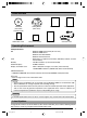
Items Included Ceiling Mount (with cover) CD-ROM (instruction manual inside) JVC Service Information Card Safety Precautions Read Me First Template Warranty Card Converter Unit Operating Environment PC Specifications OS CPU Memory Hard Disk Space Display and Video Card : Windows 2000 Professional (SP1 or later) Windows 2000 Server Windows XP Home Edition Windows XP Professional : Equivalent to or higher than Pentium 3, 500 MHz (Pentium4, 3.
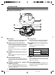
Getting Started Name and Function of Parts 䡵Ceiling Mount (Terminal Side) 9 8 7 6 5 4 1 2 3 1 Safety Wire Hang this wire to the wire fastening hook & to prevent the camera from falling down. 6 Locking Screw Ensure to fasten the camera by fastening this screw to the camera clamping bracket #. 2 [VIDEO OUT] Coaxial Cable Terminal Output terminal for composite video signals (1 Vp-p and output impedance of 75Ø). Connect this to devices such as video monitors.
䡵Ceiling Mount (Camera Terminal Side) 䡵Camera 6 & @ 0 # ^ 0 ! % $ 0 Clamping Holes (x 4) Use this hole to attach the camera to the ceiling or ceiling embedding bracket (WB-S625: sold separately). ! Camera Connection Terminal (Female) Connect this to the connection terminal (male) @ on the camera. @ Connection Terminal (Male) Connect this to the camera connection terminal (female) ! on the ceiling mount. % Dome Cover The dome cover is fragile. Take care when handling it.
Preparation Connection Examples LAN Connection VN-C625 LAN VN-C625 PC Network Connection VN-C625 VN-C625 LAN INTERNET FTP Server PC Updated images are automatically uploaded at a regular interval PC Peer-to-Peer Connection VN-C625 Cross Cable PC 12 C625_p2-24 12 05.3.
Preparation Procedure Set the camera in the following procedure. Step 1 Connection/Installation Firstly, make a hole in the ceiling, followed by connecting the power cable, LAN cable or alarm signal cable to the terminal of the ceiling mount of this camera. Next, attach the camera to the ceiling. Do not forget to attach the safety wire.
Preparation (Step 1 Connection/Installation) 1-1 Connecting Cables Cautions ● Attachment of a embedded cover in the ceiling (recess bracket) may be mandatory in certain regions. If this is so, ensure that the embedded cover (recess bracket) is securely attached before installing the camera. ● Ensure to attach the cover for the ceiling mount. Installation is not possible without attaching the cover. In addition, the cover also prevents penetration of foreign objects into the ceiling mount.
3. Lead the cable through the cover Cap (Upper) Make a slit on the (rubber) cap that is attached to the cover, followed by leading the cable through. See diagram on the left on how to make the slit. 4. Connect the cable to this camera Connect cables to the terminal on the ceiling mount. Connection cables include alarm signal cable, LAN cable, coaxial cable and that for the Converter Unit. 1 Alarm signal cable (☞Page 16) Connect this cable to devices with alarm input/output terminals.
Preparation (Step 1 Connection/Installation) 1-1 Connecting Cables (Continued) 2. Connection to Alarm Input/Output Terminal 1 Connect the alarm input/output terminals to external devices such as sensors and buzzers. 2 4 mm Flathead Screwdriver Alarm Signal Cable 1 Loosen the screws on both edges of the terminal block using a flathead screwdriver, followed by dismantling it as shown in the left diagram.
䡵 Alarm Output Terminal VN-C625 OUT Terminal IN Alarm Device Connection Example DC 12 V R Grounding Terminal GND Connect this terminal to alarm devices such as an annunciator, indicator, lamp or buzzer.
Preparation (Step 1 Connection/Installation) 1-1 Connecting Cables (Continued) 4. Connection of Coaxial Cables Polyethylene * Core Wire Mesh Wires Connecting a 5C-2V or 3C-2V coaxial cable Strip the coaxial cable according to the diagram on the left. (Unit: mm) Notes 7 17 Insulation Tape • 7C-2V coaxial cables cannot be connected directly to the terminal block. In this case, make use of the 5C-2V cable as a junction cable by connecting it to this camera.
5. Connection of Conveter Unit Power cable 5mm Press Press 2. 1. Connector Press 3. Connect the camera to AC 24 V. 1. Disconnect the connector from the supplied Converter Unit. It can be disconnected by pressing both ends as shown in the left figure. 2. Mount the power cable to the connector. Strip the cover of the power cable (about 5 mm), while pressing down the arrow portion using a flat screwdriver, insert it into the connector. to AC 24V 3. Mount the connector. 4.
Preparation (Step 1 Connection/Installation) 1-2 Attachment of Ceiling Mount Caution Ceiling Embedded Cover in Ceiling (recess bracket) • Attachment of a embedded cover in the ceiling (recess bracket) may be mandatory in certain regions. If this is so, ensure that the embedded cover (recess bracket) is securely attached before installing the camera. • Please refer to the instruction manual for the cover in use for details on installation of the embedded cover (recess bracket).
2. Fasten the ceiling mount to the ceiling Align the “™FRONT” mark on the ceiling mount in the direction that the camera is facing. Fasten the ceiling mount using the 4 screws while taking care not to catch the connection cables. Use M4-sized (No 8) screws or bolts. For woodscrews, make use of those with a diameter of 4.1 mm. Notes NT FRO FRONT Mark • Be sure to use 4 screws and attach them firmly.
Preparation (Step 1 Connection/Installation) 1-3 Inserting the CF card 1. Check to ensure that the power of the camera is not turned on 2. Remove the CF (compact flash) cover 3. Insert CF card in the direction as indicated in the diagram • Press once if the eject button is protruding • Insert the CF card all the way until you hear a "click" sound CF Cover 2. 4. Attach the CF cover dismantled in Step 2 4.
1-4 Installing the Camera 1. Attach the safety wire to prevent the camera from falling down Safety Wire Fastening Hook for Safety Wire As shown in the diagram, pull out the safety wire from the ceiling mount and hang it to the safety wire fastening hook on the camera. Be sure to connect the safety wire to prevent the camera from falling down. Cautions • Do not connect cameras other than VNC625 to the ceiling mount. Doing so may cause the camera to malfunction. • Be sure to connect the safety wire.
Preparation (Step 1 Connection/Installation) 1-4 Installing the Camera (Continued) 4. Turn the camera Camera Clamping Bracket Make sure that the camera is horizontal, followed by fitting the camera to the ceiling mount and turning it in the clockwise direction until it stops. Upon doing so, check that the the camera clamping bracket is aligned with the position of the locking screw of the ceiling mount. Turn camera in clockwise direction 5.
Settings (Step 2 Network Settings) 2-1 Installing the Software To operate this camera, you will have to install the necessary software according to the following procedure from the CD-ROM supplied. ~~~~~~~~~~~~~~~~~~~ Installing the V.Networks Controller 1. Execute "Setup.exe" in the [JVC] folder. 2. Follow instructions on the screen to install the software. 3. If installation is successful, the † "V.Networks Controller" icon will be displayed in the [Start] † [V. NETWORKS] folder.
Settings (Step 2 Network Settings) 2-2 Setting PC's IP Address [Windows XP] Upon installing the camera, set the IP address of the PC that is used to operate this camera. For Windows XP, set according to the following procedure. (For Windows 2000, ☞ Page 28) Note Under a DHCP environment and when the IP address assigned to V. Networks is already known, it will not be necessary to perform 2-2 "Setting PC's IP Address" as the PC's IP address is automatically acquired from the DHCP server. 1. Click .
3. Select [Internet Protocol (TCP/IP)] and click [Properties]. 1 Select [Internet Protocol (TCP/IP)]. 2 Click [Properties]. 4. Select [Use the following IP address], set the [IP address] and [Subnet mask] and click . 1 Select [Use the following IP address]. 2 Set [IP address] to 192.168.0.3. Note • Make sure to note down the original IP address before changing. • Do not use the same IP address elsewhere within the same network environment. 3 Set Subnet mask to an appropriate value.
Settings (Step 2 Network Settings) 2-2 Setting PC's IP Address [Windows 2000] Upon installing the camera, set the IP address of the PC that is used to operate this camera. For Windows 2000, set according to the following procedure. 1. Click . • Select [Settings] and click [Properties]. 2. Double-click [Network and Dial-up Connection]. 3. Double-click [Local Area Connection]. 1 Click . 2 Select [Internet Protocol (TCP/IP)]. 3 Click . 28 C625_p25-41 28 05.3.
4 Select [Use the following IP address]. 5 Set [IP address] to 192.168.0.3. 6 Set Subnet mask to an appropriate value. Ask the network administrator if necessary. 4.Click . 29 C625_p25-41 29 05.3.
Settings (Step 2 Network Settings) 2-3 Setting IP Address for this Camera Using the "VN-C625U Setup Tool" Set the IP address for VN-C625 using the "VN-C625U Setup Tool" that has been installed. (This "VN-C625U Setup Tool" only allows connection of VN-C625.) Caution • Upon turning on the power of this camera, it may take about 60 seconds before it can be connected to the PC. • At the factory, DHCP is enabled for VN-C625.
2. Check settings. 1 Select whether to use DHCP. Note The IP address of the DHCP server and other information can be checked when [DHCP] is selected. 2 Change the IP address to the one assigned to or approved by the administrator. 3 Set Subnet mask to an appropriate value. Ask the network administrator if necessary. 4 Click For other settings, ☞ next page 3. Click . . [V.Networks ID] works as an identification code set to VN-C625. Only alphanumeric characters can be used.
Settings (Step 2 Network Settings) 2-4 Other Settings Using the "VN-C625U Setup Tool" Perform setting of details other than the IP address using the "VN-C625U Setup Tool" that has been installed. 1. Select [Start] † [Programs] † [V.NETWORKS] † [VN-C625U Setup Tool] to start up the "VN-C625U Setup Tool". ☞ Page 33 ☞ Page 46 ☞ Page 52 ☞ Page 48 ☞ Page 49 ☞ Page 50 ☞ Page 54 ☞ Page 55 ☞ Page 55 ☞ Page 45 ☞ Page 42 ☞ Page 36 ☞ Page 44 ☞ Page 34 2.
2-4 Other Settings Using the "VN-C625U Setup Tool" (1. Password Setting) PCs (users) connected to this camera are regulated via an access protection function which requires a password entry. Passwords can be set or canceled using the "VN-C625U Setup Tool". A different password can be set for each of the 3 authorization levels, namely user, operator and administrator. Authorization Level User Operator Administrator Allowed Access Viewing of motion images only All operations using the V.
Settings (Step 2 Network Settings) 2-4 Other Settings Using the "VN-C625U Setup Tool" (2. Multicast) Selecting Multicast mode allows VN-C625 to send the same image data to multiple PCs on the network at one time without lowering the frame rate. 1. Start up the "VN-C625U Setup Tool" and select [Multicast]. The [Multicast Setting] screen will be displayed. 1 Select [Multicast Mode]. 2 Select the mode for acquiring images. : Set to Normal when using a narrow bandwidth network.
It is possible to search for the multicast address of a VN-C625 that is connected to the network. 1. Start up the "VN-C625U Setup Tool". Click . 2. The [V.Networks Search] screen is displayed. Click . 3. The [Multicast Address Search] screen is displayed. 1 Select . Start search. 4. The search result is displayed. 35 C625_p25-41 35 05.3.
Settings (Step 2 Network Settings) 2-4 Other Settings Using the "VN-C625U Setup Tool" (3. Alarm Setting) This section describes procedures for alarm setting. Alarm Input • When there is an input of signals to the alarm input terminal on the ceiling mount. (☞ Page 16 "Alarm Input Terminal") • When motion is detected. (☞ Page 46 "Motion Detection Setting") • Upon movement to a new position. • When there is a change in the Black & White mode.
2. Click the [Other Triggers] tab on the [Alarm Setting] screen. 5 6 7 4 3. When setting is complete, click followed by . 4. Click the [Alarm Output] tab on the [Alarm Setting] screen. 8 9 4 5. When setting is complete, click followed by . 37 C625_p25-41 37 05.3.
Settings (Step 2 Network Settings) 2-4 Other Settings Using the "VN-C625U Setup Tool" (3. Alarm Setting) (Continued) Alarm Input Item 1 Alarm 1/Alarm 2 Mode Detect Mode Alarm Output Function/Set Value Initial Value This section describes setting procedures for alarm input. — Not Available For selecting whether to enable or disable the input signals. Set Values : Available, Not Available Make For selecting the method for detecting input signals. Make : Detect input signals at the "Make" contact point.
Item 1 Alarm 1/Alarm 2 Message Packet Alarm FTP Shutdown Function/Set Value Initial Value (Continued) — For setting whether to send alarm packets to the PC when there Not Available is alarm input. Not Available : Do not send alarm packets. Available : Send alarm packets. For operation according to the [Alarm FTP] in the FTP Client Not Available feature when there is alarm input. Please refer to FTP Client Settings (☞ Page 50) for details on alarm FTP.
Settings (Step 2 Network Settings) 2-4 Other Settings Using the "VN-C625U Setup Tool" (3. Alarm Setting) (Continued) Alarm Input (Continued) Function/Set Value Initial Value Press here to display the IP address of the PCs to which an alarm notification is sent. ("Distribution Address List" Screen) To delete a distribution address, select the IP address to delete, followed by pressing the Delete button. — Item 4 List Notes • The list allows setting of up to 10 addresses.
Alarm Output Function/Set Value Initial Value This section describes the setting procedures for alarm output. Set Values : ON, OFF Select the alarm output method. Output OFF : Output alarm signals when the Alarm Output 1 or Alarm Output 2 terminal is connected to the GND terminal. Output ON : Output alarm signals when the Alarm Output 1 or Alarm Output 2 terminal and the GND terminal are disconnected from each other. Level : Continue output of alarm signals throughout the alarm input process.
Settings (Step 2 Network Settings) 2-4 Other Settings Using the "VN-C625U Setup Tool" (4. Recording Setting) This function is used to perform settings for local recording, which records camera images to the CF card when the alarm is activated. Please purchase the CF card separately. (☞ Page 22) ● When an alarm is activated, recording can be performed via "local recording", where camera images are saved into a CF card, or via the V.Networks Controller, where these are saved into the hard disk of the PC.
● Setting the [Advance] screen 4 For setting the recording action when the memory capacity of the CF card is full. One of the following actions can be selected. (Internal memory capacity is 8 MB.) • Stop recording until an availability is made in the CF card. • Remove old files that have exceeded a specific number of days. (If the number of days is set to "0", files will be deleted starting with the oldest one.
Settings (Step 2 Network Settings) 2-4 Other Settings Using the "VN-C625U Setup Tool" (5. Private Mask Setting) Use the Private Mask function to gray out areas on the screen that are to be excluded during shooting. Up to 4 private masks can be set for each display screen and a total of 8 private masks for each camera. 1. Start up the "VN-C625U Setup Tool" and select [Private Mask]. The [Private Mask] screen will be displayed. (Controller Used for Private Mask Setting) 1 Set [Private Mask] to "ON".
2-4 Other Settings Using the "VN-C625U Setup Tool" (6. Motor Limit Setting) When areas that are not required are included during shooting due to the installation position of the camera, make use of the Motor Limit function to set the shooting range. 1. Start up the "VN-C625U Setup Tool" and select [Motor Limit]. When [Mode] is set to "Available", the Pan Limit function will be enabled and panning (horizontal) actions can be controlled.
Settings (Step 2 Network Settings) 2-4 Other Settings Using the "VN-C625U Setup Tool" (7. Motion Detection Setting) For setting the motion detection function, which activates the alarm when there is motion in the camera image. Perform the following procedure to set area for motion detection. 1. Start up the "VN-C625U Setup Tool", select [Alarm Setting] and set [Motion Detection] to "Available". (☞ Page 40 "Other Trigger") 2. Select [Motion Detect] under [VN-C625 Setup Tool].
3. Perform area setting. Image of the position that is selected as the Fixed area in 2 of Step 2 will be displayed. 1 Click and drag the mouse to select the detection area. To cancel the detection area (displayed in yellow), right-click and drag the mouse. Area for which motion is detected will be displayed in red. 2 For setting the sensitivity level of motion detection. Drag towards the right to increase and left to decrease the sensitivity level.
Settings (Step 2 Network Settings) 2-4 Other Settings Using the "VN-C625U Setup Tool" (8. Web) A designated html file can be set as the default page for the web browser using this setting. 1. Start up the "VN-C625U Setup Tool" and select [Web]. Specify settings for viewing using the web browser. When "Disable" is checked, viewing of images from other PCs will be disabled. Set the use of a default HTTP page. Specify the html file to be used as the default page when the [Available] box is checked.
2-4 Other Settings Using the "VN-C625U Setup Tool" (9. FTP Server) HTML pages or gif and jpeg images can be uploaded to this camera by using the FTP Client software. 1. Start up the "VN-C625U Setup Tool" and select [FTP Server]. Set the FTP Server Function to "ON" or "OFF". Notes ● The FTP user name is fixed as "Administrator". Use the administrator level password as the FTP password. ● About 256 KB is allocated as the FTP's user area. ● All uploaded files will be placed under the /user folder.
Settings (Step 2 Network Settings) 2-4 Other Settings Using the "VN-C625U Setup Tool" (10. FTP Client Setting) VN-C625 is equipped with a "FTP Client" feature that uploads still images to the existing FTP server on a regular interval. This feature enables simultaneous image monitoring by many clients (from many locations). 1. Start up the "VN-C625U Setup Tool" and select [FTP Setting]. The [FTP Setting] screen will be displayed. 1 Continuous FTP Check [Available] to enable the FTP feature.
3 4 Username Enter the user name to use for verification with the FTP server. It can be set as "anonymous". Password Enter the password to use for verification with the FTP Server. Characters entered are displayed as " * ". Note To resume operation, set 1 [Continous FTP] to "Available". 0 Filename *.jpg : Check this item to upload file with the name that appears in the position indicated as " * ". 5 FTP Serverv IP Address Enter the IP address of the FTP server at the upload destination.
Settings (Step 2 Network Settings) 2-4 Other Settings Using the "VN-C625U Setup Tool" (11. Black & White Setting) 1. Start up the "VN-C625U Setup Tool" and select [B & W]. The [Black & White] screen will be displayed. 1 2 3 4 Click . The [Trigger Setting] screen will be displayed. Set the [Time Trigger] for switching the Black & White mode at the specified time. Time1/Time2 Mode Black and White : Switches to the Black & White mode upon reaching the specified time.
1 Mode For setting the function on switching from Color to Black & White mode. Black & White : Black & White mode at all times. : Black & White mode at all times. Color : Do not switch to the Black & White mode. Auto : Switches automatically to the Color mode when brightness level of the object is high, and to the Black & White mode when brightness level of the object is low. 3 One Push AF For setting whether to adjust focus automatically when switching between the Color / Black & White modes.
Settings (Step 2 Network Settings) 2-4 Other Settings Using the "VN-C625U Setup Tool" (12. Time Setting) This section describes how to set the standard time for VN-C625. NTP can also be used for this function. 1. Start up the "VN-C625U Setup Tool" and select [Time]. There are 2 methods of setting, depending on whether NTP is to be used. When NTP is not used 1 Set the date and time. 2 Allows reference of PC time. When NTP is used 1 Enter the IP address of the NTP server to be used. 2 Set the time zone.
2-4 Other Settings Using the "VN-C625U Setup Tool" (13. Memory Information) It is possible to check the memory capacity of VN-C625. 1. Start up the "VN-C625U Setup Tool" and select [Memory Info]. 1 Check the available memory space. (The built-in memory capacity of this camera is about 8000 KB.) 2-4 Other Settings Using the "VN-C625U Setup Tool" (14. Auto Return Setting) This is used to set the Auto Return function, which returns the camera automatically to its original mode after a manual operation. 1.
Settings (Step 2 Network Settings) 2-5 Registering Connected Camera Using the "V.Networks Controller" The connected camera can be registered with the installed "V.Networks Controller". 1. Select [Start] † [Programs] † [V. NETWORKS] † [V.Networks Controller] to start up the "V.Networks Controller". 2. Select [File] and [New]. 3. The [New] screen will be displayed. 1 Enter the [IP Address]. Note In a DHCP environment, enter the IP address that is assigned to this camera by the DHCP server.
4. Connect to VN-C625. Notes To connect to a VN-C625 for which DHCP setting is possible, either one of the following environments will be required. • Environment where no DHCP server exists. • Environment with a DHCP server that clearly defines the IP and MAC addresses assigned to VN-C625. 57 VN-C625_p42-p57_2_24 57 05.3.
Settings (Step 3 Setting Using the V.Networks Controller) 3-1 Starting Up V.Networks Controller The installed "V.Networks Controller" can be used to monitor camera images. In addition, recording/playback operations and setting of frame rate for camera images are also possible. 1. Select [Start] † [Programs] † [V. NETWORKS] † [V.Networks Controller] to start up the "V.Networks Controller". 1 Select the camera to connect to from the pull-down menu for the camera.
3-2 Features that Allow Setting Using the V.Networks Controller The V.Networks Controller can be used to perform settings for image size and alarm. 1 2 3 1File New : Creates a new file if the camera is connected for the first time. Delete : Deletes a file. Motion Detection Standby : Select the camera for which the Motion Detection Standby function is to be enabled. Exit : Exits the controller. 2View Image Size : Sets the image display size.
Settings (Step 3 Setting Using the V.Networks Controller) 3-2 Features that Allow Setting Using the V.Networks Controller (Continued) 4 5 5Help 4Setting Quality : For setting the compression rate and image quality. (☞ Page 63) Frame rate : For setting the number of camera images to send per second. (☞ Page 67) Position Memory : For setting preset positions. (☞ Page 68) Alarm Reg : Alarm operation will be enabled if this item is checked. Alarm Setting : For setting alarm actions for each alarm.
3-3 Motion Detection Standby The "Motion Detection Standby" function enables automatic connection upon receiving notifications on detected motion from VN-C625 when the V.Networks Controller has been started up. 1. Select [File] and [Motion Detection Standby]. 2. Select a camera. 1 Select the camera for which the Motion Detection Standby function is to be enabled. 1 Click 3. Click . . 61 C625_p58-p79 61 05.3.
Operations (Step 3 Setting Using the V.Networks Controller) 3-4 Image Size and Inversion The "V.Networks Controller" can be used to set the size of the motion image window as well as to invert an image. 1. Select [View]. 2. Specify [Image Size] and [Upside Down] settings. Notes ● Setting to the Fine mode enables display of image details. Images of moving objects shot in this mode may be blurred, but this is not a malfunction. ● Fine mode can only be used with the 640 x 480 resolution. Click .
3-5 Image Quality Setting The "V.Networks Controller" can be used to perform image quality settings such as compression level and white balance. 1. Select [Setting] and [Quality]. 2. Change the set values. (For description of each function, ☞ next page) * When the [Distribution control ON] is selected, the following screen will be displayed. Image Quality Setting (☞ Page 64) Resets all set values on image quality to their factory settings.
Operations (Step 3 Setting Using the V.Networks Controller) 3-5 Image Quality Setting (Continued) Image Quality Setting Item Function/Set Value Initial Value Distribution Control Set the maximum transmission control. OFF Setting of compression level is possible when this is set to "OFF", OFF 2 and images will be sent out at the specified compression level. The smaller the value, the lower the compression level and hence a higher image quality. However, data volume will also increase.
Item Average : Peak Shutter Function/Set Value Initial Value Sets the method of exposure detection according to ratio be8:2 tween the average and peak values. • Large Average value : Use this setting when areas other than those highlighted are dark and unclear. (Example: 10:0) • Large Peak value : Use this setting when halation occurs at the highlighted areas. Use this setting when areas other than those highlighted are dark and unclear.
Operations (Step 3 Setting Using the V.Networks Controller) 3-5 Image Quality Setting (Continued) Lens Item Iris Focus Zoom Function/Set Value Initial Value Set the method for adjusting the lens iris. Auto Auto : Adjusts iris automatically to the default state. Auto+ : Adjusts iris automatically to a level brighter than the default state. Auto: Adjusts iris automatically to a level darker than the default state. Manual : Use this setting to adjust the iris manually. Adjusts the focus.
3-6 Frame Rate The "V.Networks Controller" can be used to set a maximum value for the frame rate, which indicates the number of live image updates per second. 1. Select [Setting] and [Frame rate]. 2. Set the [Frame Rate]. Set the maximum number of images per second that are sent from VN-C625.
Settings (Step 3 Setting Using the V.Networks Controller) 3-7 Preset Position Setting The "V.Networks Controller" can be used to set the preset position for the connected camera. 1. Select a camera. 1 Select a camera for setting from the pulldown menu for the camera. 2. Select [Setting] and [Position Memory]. 1 Select a position. 2 The title of the current position will be displayed. Enter here to change the title. (Up to 32 single-byte characters (32 bytes)) 3 Adjust the angle of view and zoom.
3-8 Alarm Setting The "V.Networks Controller" can be used to set the action to be taken when an alarm signal is received. 1. Select [Setting] and [Alarm Setting]. 2. Change the set values. (For description of each function, ☞ next page) Setting may be performed for the [Motion Detection], [Alarm 1], [Alarm 2], [Relay Alarm], [Preset Position] and [Black & White]. 1 2 3 4 (Setting of 1 and 2 are disabled when in the Relay Alarm mode.) 3. When setting is complete, click . 69 C625_p58-p79 69 05.3.
Settings (Step 3 Setting Using the V.Networks Controller) 3-8 Alarm Setting (Continued) 1 2 Message Message entered in the textbox will be displayed when there is an alarm input. (Up to 100 single-byte characters) 3 Playing wave file Plays back a designated Wave file when there is an alarm input. Click the [Browse] button to specify a file. Note Recording Starts recording when there is an alarm input. Non-stop : Recording continues until the Stop button is pressed.
3-9 Pan/Tilt Setting The "V.Networks Controller" can be used to perform pan/tilt settings. 1. Select [Setting] and [Pan/Tilt Setting]. 2. Perform Pan/Tilt settings. Pan/Tilt Speed Sets the speed of movement when Angle Step is set to "0". Variable: Alters the pan/tilt speed automatically according to the zoom of the lens. The speed lowers when the zoom position is set to the Tele-end, and increases when set to the Wide-end. Speed 1 to Speed 8: Sets the Pan/Tilt speed.
Settings (Step 3 Setting Using the V.Networks Controller) 3-10 Auto Pan Setting The "V.Networks Controller" can be used to set the Auto Pan operation, which moves the camera from a preset position horizontally at a constant speed. Return An ti-c loc kw ise ckw Clo ise 1. Select a camera. 1 Select the camera for setting from the pull-down menu for the camera. 2. Select [Setting] and [Auto Pan Setting]. 1 Select [Auto Pan Setting] from the [Setting] pull-down menu. 72 C625_p58-p79 72 05.3.
3. Perform setting. 1 Set Auto Pan operation using the [Action Mode] pull-down menu. • Right : Rotates horizontally in the clockwise direction from the start position. • Left : Rotates horizontally in the anticlockwise direction from the start position. • Return : Moves continuously between the start and return positions horizontally. 2 Set the speed of operation from the [Speed] pull-down menu. (Set value: High, Normal, Low) 3 Set the start position of the operation.
Settings (Step 3 Setting Using the V.Networks Controller) 3-11 Auto Patrol Setting The camera can be moved to multiple positions based on the preset sequence and time. Use this setting to view specified positions in sequence. Perform setting for each camera. 1. Select a camera. 1 Select a camera for setting from the pulldown menu for the camera. 2. Select [Setting] and [Auto Patrol Setting]. 1 Select [Auto Patrol Setting] from the [Setting] pull-down menu. 74 C625_p58-p79 74 05.3.
3. Perform setting. 1 Set the mode. Setting can be performed from Modes 1 to 3. Click the tab of the respective mode for setting. 2 Set the Position Number. For each Patrol Number, set a Position Number to move to in sequence. 3 Set the time interval. Auto Patrol No. Auto Patrol operates in the sequence of these numbers. Set the time for displaying each position set in 2. (Unit: seconds) 4. Close the window. When setting is complete, click to close the window.
Settings (Step 3 Setting Using the V.Networks Controller) 3-12 Auto Trace Setting Details of manual camera operations can be stored and reproduced. 1. Select a camera. 1 Select a camera for setting from the pulldown menu for the camera. 2. Select [Setting] and [Auto Trace Setting]. 1 Select [Auto Trace Setting] from the [Setting] pull-down menu. 3. Start to memorize operation. 1 Click . Memorization of Auto Trace will start and subsequent pan/tilt as well as zoom operations will be stored.
4. Close the window. 1 When memorization is complete, click to end. 2 When setting is complete, click to close the window. Caution ● There is a limit to the length of recording time. Recording can be performed up to 30 seconds. However, this may shorten depending on its frequency of use. Be sure to perform operation check upon setting. Note For starting and stopping operations of Auto Pan, Auto Patrol and Auto Trace, please refer to Page 59. 77 C625_p58-p79 77 05.3.
Operations (Step 3 Setting Using the V.Networks Controller) 3-13 Time Stamp The "V.Networks Controller" can be used to set the time stamp that displays date/ time on camera images. The displayed time/date will be recorded. 1. Select [Setting] and [Time Stamp]. 2.Perform setting. 1 Select [Visible]. 2 Select the display style in [Style]. Year, month and day are represented as "YYYY", "MM" and "DD" respectively. Hour, minute and second are represented as "HH", "MM" and "SS".
3-14 Changing Registered Information The "V.networks Controller" can be used to change information such as the preset connection method for a camera. 1. Select [Setting] and [Property]. 2. Perform setting. 1 Change the camera. Cannot be changed. 2 Recorded files will be stored in the folder specified here. 3 Select the mode for image acquisition. *For details, refer to Page 56. 4 Set whether to [ON]. 3. When alteration is complete, click .
Operations (Step 4 Operation Using the V.Networks Controller) 4-1 Features that Allow Operation Using the V.Networks Controller The "V.Networks Controller" can be used to select a camera as well as record/play back camera images. (The controller screen is identical to other V.Networks versions, and there are functions that cannot be operated from VN-C625) 1 2 3 4 5 6 7 1 CAMERA Displays the name of the connected camera. You can also select the connected camera (pull-down menu).
# @ ! 0 8 8 Pan/Tilt button For adjusting the Pan/Tilt position. Use Angle Step to set the operating angle for every single operation of the Pan/Tilt button. Set the Pan/Tilt operating speed using the [Pan/Tilt Setting] item under [Setting]. (☞ Page 71) 9 HOME For moving the camera to the home position. 0 Zoom button and Zoom bar For adjusting the zoom position.
Operations (Step 4 Operation Using the V.Networks Controller) 4-2 Record/Stop The "V.Networks Controller" can be used to save camera images to a file. 1. Click the [REC] button. Connected Camera (Saved in a folder under this name) Recording Format [REC] Indicator 2. 1. (Motion Image Window) [REC] Indicator 2. Click the [Stop] button. Stops recording and the [Recording] and [REC] indicators will disappear. (Click the [Snap Shot] button to record only 1 frame of the displayed image.
4-3 Playback Files saved upon "REC" using the "V.Networks Controller" can be selected and played back. (Playback of a file and display of motion images cannot be performed at the same time.) 1. Click the [PLAY] button. [PLAY] button 2. Select the file to play back on the [Playback File] screen, followed by clicking . To play back local recording files, click [Refer to Local Rec.] to select a file. Select [Refer to Local Rec.]. The file name is represented by the time that recording started and ended.
Operations (Step 4 Operation Using the V.Networks Controller) 4-3 Playback (Continued) 3. Click . 4. The [Playback] screen is displayed. Slidebar • Moves towards the right as playback time progresses. • It can be dragged using the mouse. [Stop] button [Pause] button [Play] button 84 C625_p80-p94 84 05.3.
4-4 Cautions on Record/Play Functions Record/Playback Time • Do not record or play back a file that exceeds 2 GB using the "V.Networks Controller". Random access to data beyond 2 GB is not possible with standard Windows applications. Reference: Approximate recording time for 2 GB data (At frame rate of 5 fps) Image Size 320 x 240 640 x 480 Data Size Per Image Approx. 15 KB Approx. 50 KB Approximate Recording Time 6 hours 2 hours 85 C625_p80-p94 85 05.3.
Operations (Step 4 Operation Using the V.Networks Controller) 4-5 Snapshot The "V.Networks Controller" can be used to save video images currently displayed or playback images as still image files. 1. Click the [Snap Shot] button. Note Only JPEG files can be saved as snapshot files. [Snap Shot] button 2. The [Snap] screen will be displayed. 1 Select [File] and [Save]. 3. The [Save As] screen is displayed. 1 Specify a folder for saving the file. 2 Enter a File name. 3 Click to save the snapshot.
Operations (Step 5 Operating Using a Web Browser) In addition to the controller software supplied, web browsers can also be used to view still/motion images as well as to perform various settings. 5-1 Operating Environment The following environment will be required to view/operate VN-C625 using a web browser. The PC in use shall also meet requirements on the operation environment stated in this manual (☞ Page 9). PCs installed with the following web browsers ● Internet Explorer 4.x, 5.x or 6.x.
Operations (Step 5 Operating Using a Web Browser) 5-2 Access Authorization Level The configuration of URLs (web pages) in VN-C625 is illustrated as follows. Access Authorization Level << User >> << Operator Top page Still image page >> << Administrator >> (index-e.html) (still-e.html) Live image page (java-e.html) Still image URL (still.jpg) Serverpush moving image URL (push.jpg) Java moving image URL (mjpeg.class) Control (pantilt-e.html) Settings ( java config-e.
5-3 Starting Up the Web Browser Specify the default web page address of VN-C625 as the page to view using the web browser. (Upon entering the factory setting of the IP address, the web browser will display the front page of VN-C625.) Note You may not be able to specify the IP address directly if a proxy server is set for accessing the Internet. In this case, change the proxy settings to enable direct specification. 1. Start up the web browser. "http://192.168.0.2/index-e.
Operations (Step 5 Operating Using a Web Browser) 5-4 Setting Using the Web Browser Web browsers can be used to set the IP address, image quality or FTP. 1. Display the Top page. Still Image of VN-C625 Camera image at the point when browsing starts is displayed. . Click (Click once to jump to these pages.) Top Page 90 C625_p80-p94 90 05.3.
2. The [Settings] page will be displayed.
Operations (Step 5 Operating Using a Web Browser) 5-4 Setting Using the Web Browser (1. Other Settings) Other settings: http://******/config-e.html ("******" represents the URL of VN-C625) Setup can be performed by specifying details for items in [Other Settings]. (This is also possible using the "VN-C625U Setup Tool" supplied.) 1 2 3 4 5 6 7 8 9 0 ! @ # Click to update settings. 92 C625_p80-p94 92 05.3.
5-4 Setting Using the Web Browser (1. Other Settings) (Continued) Description of Items in [Other Settings] Item DHCP 1 2 IP Address 3 Subnet Mask 4 Default Gateway 5 Host Name 6 MAC Address 7 Program Version 8 Password (Within 8 characters) User Level Operator Level Administrator Level 9 Cache Control 0 FTP Server Function ! Default Page Meaning Select [Available] when DHCP is used. Change the IP address to the one assigned or approved by the network administrator.
Operations (Step 5 Operating Using a Web Browser) 5-4 Setting Using the Web Browser (1. Other Settings) (Continued) Description of Items in [Other Settings] Meaning Item ! Default Page (Continued) Available/Not Available Set to "Available" when using the default page function and to "Not Available" when not in use. File Name Enter the html file name that is to be used as the default page.
5-4 Setting Using the Web Browser (2. Control) Control window: http://*****/pantilt-e.html ("*****" represents the URL of VN-C625) 1 5 6 2 3 4 7 8 1 Current Position Displays the current Pan/Tilt and Zoom positions. 5 One Push AF Click to adjust focus automatically. 6 Speed 2 PAN/TILT/ZOOM For moving the camera to the specified position upon pressing the [Move] button. For setting the speed of the Pan/Tilt operation.
Operations (Step 5 Setting Using the Web Browser) 5-4 Setting Using the Web Browser (3.Image Setting) Image Setting window: http://*****/configimage-e.html ("*****" represents the URL of VN-C625) 1 2 3 4 5 6 7 8 9 0 ! Click to reset all values to their factory settings (default values). Click to apply settings and to save the set values. to apply settings without saving the set values.
1 Focus For selecting the mode of focus. Easy Auto Focus : Focus will be adjusted automatically upon performing Pan/Tilt or Zoom operations on the camera. Manual : Adjust focus manually. 2 Color Level Adjusts the color level of video signals. (Set value: -5 to 5) 3 Enhance Level Sets the contour enhancement which controls the sharpness on the monitor screen. (Set value: -5 to 5) 4 Pedestal Level Sets the pedestal level (black level) of video signals.
Operations (Step 5 Setting Using the Web Browser) 5-4 Setting Using the Web Browser (4. PAN/TILT Setting) PAN/TILT Setting window: http://*****/configpantilt-e.html ("*****" represents the URL of VN-C625) This section describes procedures to perform various PAN/TILT settings. 1 2 Click to apply settings and to save the set values. Click to apply settings without saving the set values. These settings will be cleared upon turning off the power of VN-C625, and the previous settings will be restored.
5-4 Setting Using the Web Browser (5. Position Memory Setting) Position Memory Setting window: http://*****/position-e.html ("*****" represents the URL of VN-C625) This section describes procedures for setting preset positions of the connected camera. Select a position. Enter a position title. (Up to 32 single-byte characters (32 bytes)) Position of the current angle of view will be displayed. Adjust the angle of view and zoom. Adjust the image quality. to display the [Image Click Settings] screen.
Operations (Step 5 Setting Using the Web Browser) 5-4 Setting Using the Web Browser (6. View Setting) View Setting window: http://******/viewconfig-e.html ("******" represents the URL of VN-C625) Click to apply settings and to save the set values. to apply settings without Click saving the set values. These settings will be cleared upon turning off the power of VN-C625, and the previous settings will be restored.
5-4 Setting Using the Web Browser (7. Alarm Setting) Alarm Setting window: http://******/alarm-e.html ("******" represents the URL of VN-C625) This page describes procedures for setting VN-C625 operation upon input of alarm signals. 1 2 3 4 5 Click to apply settings and to save the set values. Click to apply settings without saving the set values. These settings will be cleared upon turning off the power of VN-C625, and the previous settings will be restored. 101 C625_p95-p114 101 05.3.
Operations (Step 5 Operating Using a Web Browser) 5-4 Setting Using the Web Browser (7. Alarm Setting) (Continued) 䡵 Alarm In 䡵 Other Triggers For specifying the camera operation upon input of alarm signals. 1 IN1/IN2 For setting alarm activation via methods other than alarm input.
5-4 Setting Using the Web Browser (8. FTP Setting) FTP Client Setting window: http://******/ftp-e.html ("******" represents the URL of VN-C625) Notes ● What is an FTP Client? It is a feature that uploads VN-C625 images (still images) to the existing FTP server at a regular interval. By doing so, it is possible to make use of the server's image distribution services, thereby enabling distribution of images to a considerably larger number of clients.
Operations (Step 5 Setting Using the Web Browser) 5-4 Setting Using the Web Browser (8. FTP Setting) (Continued) Meaning Item 1 FTP Function For setting whether to use the FTP function. Check this box when the function for uploading JPEG images to the FTP server is to be used regularly. Upload Specify the time interval at which images are uploaded to the FTP Interval server. (Set value: 0 to 65535 seconds) Alarm FTP Check this box to upload JPEG images to the FTP server when there is an alarm input.
5-4 Setting Using the Web Browser (9. Auto Pan Setting) Auto Pan Setting window: http://******/autopan-e.html ("******" represents the URL of VN-C625) 1 2 3 8 4 5 6 7 1 Mode For setting the mode of Auto Pan operation. (Set value: Right, Left, Return) 2 Speed For setting the speed of Auto Pan operation. (Set value: Normal, High, Low) 3 Current Displays the current Pan/Tilt/Zoom positions. 7 Quality Upon clicking , the current image will switch to the image quality setting during Auto Pan operation.
Operations (Step 5 Setting Using the Web Browser) 5-4 Setting Using the Web Browser (10. Auto Patrol Setting) Auto Patrol Setting window: http://******/autopatrol-e.html ("******" represents the URL of VN-C625) For setting the Auto Patrol operation. Mode Select the mode for which settings are to be changed. (Set value: Mode 1, Mode 2, Mode 3) Position Number For each Patrol Number, set a Position Number to move to in sequence.
5-4 Setting Using the Web Browser (11. Auto Trace Setting) Auto Trace Setting window: http://******/autotrace-e.html ("******" represents the URL of VN-C625) For setting the Auto Trace operation. 1 Press to display the [Record Start Confirmation Screen]. Memorization of Auto Trace will start and subsequent upon clicking Pan/Tilt as well as Zoom operations will be stored. (Approximately 30 seconds) 2 For manual Pan/Tilt and Zoom operation. 3 To end a recording operation, click .
Operations (Step 5 Setting Using the Web Browser) 5-4 Setting Using the Web Browser (12. Black & White Setting) B & W Setting window: http://******/bwcongig-e.html ("******" represents the URL of VN-C625) For performing setting related to switching between the Color and Black & White modes. 1 Mode Color : Color mode at all times. Black & White : Black & White mode at all times. Auto : For switching automatically between the Black & White and Color modes according to the brightness of the object.
5-4 Setting Using the Web Browser (14. Private Mask Setting) Private Mask Setting window: http://******/privatemask-e.html ("******" represents the URL of VN-C625) For setting the Private Mask function. 1 A mask will appear on the screen when "ON" is selected. Even when mask settings are performed, a mask will not appear if this is set to "OFF". to view the mask that is Click currently set. 2 Select the mask number for which settings are to be changed.
Operations (Step 5 Operating Using a Web Browser) 5-4 Setting Using the Web Browser (15. Limit Setting) Limit Setting window: http://******/pantiltlimit-e.html ("******" represents the URL of VN-C625) For setting restrictions on Pan/Tilt operation. 1 2 3 4 5 6 7 8 1 Function 6 Left Side 2 Current 7 TILT Limit For setting the operation. When [ON] is selected, the Pan Limit function will be enabled and panning (horizontal) actions can be controlled. Displays the current Pan/Tilt/Zoom positions.
5-4 Setting Using the Web Browser (16. Auto Return Setting) Auto Return Setting window: http://******/selfreturn-e.html ("******" represents the URL of VN-C625) For performing settings to return camera to its original mode upon manual operation. Return Action Returns camera automatically to a preset operation when the camera is left unoperated for some time after a manual operation.
Operations (Step 5 Operating Using a Web Browser) 5-5 Viewing Still Images Still Image Page: http://******/still-e.html ("******" represents the URL of VN-C625) This page can only be used to view still images. Camera image at the point when browsing starts is displayed. To update the image, use [Refresh] or [Reload] on the web browser. To save the displayed image, use [Save As] on the web browser. Hyperlink to Home Page 112 C625_p95-p114 112 05.3.
5-6 Viewing Live Images Live Image Page: http://******/java-e.html ("******" represents the URL of VN-C625) This page can only be used to view motion images. Camera images are automatically updated and displayed as a motion image. Notes Do not use the [Save As] function as this page is not created to support the [Save As] function on the web browser. Similarly, do not use the [Save As] function for web pages as they also do not support this function.
Operations (Step 5 Operating Using a Web Browser) 5-7 Image Link Output images of VN-C625 can be pasted onto a separately created web page. Images (still and motion) captured using VN-C625 can also be incorporated and displayed on a user-created web page. Displaying a still image: Still images can be displayed by creating a web page containing the following:  PAGE 115
Others Troubleshooting Symptom Causes/Remedial Actions Forgotten the VN-C625 IP address that was changed using the "VN-C625U Setup Tool". ● Use the "Search" function in the "VN-C625U Setup Tool" to view the list of IP addresses for cameras connected to the network. (☞ Page 30) Unable to record. ● Has the folder for saving images been deleted? Check to ensure that the folder exists. (☞ Page 79) ● Is the hard disk of your PC full? Check the available hard disk space on your PC and delete unwanted files.
Others Troubleshooting (Continued) Symptom Causes/Remedial Actions Unable to perform camera control or settings acquired are incorrect for a span of about 60 seconds after turning on the power. ● About 60 seconds are required for initialization of the camera to complete upon turning on the power. To perform camera control or acquire settings, do so by allowing an interval of at least 60 seconds after turning on the power. Video images cannot be displayed smoothly.
Others Specifications 䡵 Camera Image pickup device Sync system Scanning frequencies 䡵 Rotating Table (Pan/Tilt Mechanism) : 1/4-inch type, interline transfer CCD, 768 (H) x 494 (V) : Internal Panning range : 360˚ endless revolution Panning speed : 1.5˚/s to 180˚/s Tilting range : 0˚ to 90˚ (Horizontal to straight downwards) Tilting speed : 1˚/s to 120˚/s : 15.734 kHz (Horizontal), 䡵 LAN Standard 59.
Others 190 127 36 䡵 External Dimensions [Unit: mm] SR 55 φ120 83.5 46 71 70 䡵 Ceiling Mount Hole [Unit: mm] Screw Positions e ol H 46 g tin n ou M 5 φ7 Screw Positions 83.5 * Specifications and appearance of this unit and related products are subject to change for product improvement without prior notice. 118 C625_p115-p118 118 05.3.
VN-C625 DOME TYPE NETWORK CAMERA R R is a registered trademark owned by Victor Company of Japan, Limited. is a registered trademark in Japan, the U.S.A., the U.K. and many other countries. © 2005 Victor Company of Japan, Limited. VN-C625_In_Cover 2 LWT0248-001A 05.3.