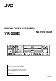
DIGITAL VIDEO RECORDER INSTRUCTIONS VR-509E OPEN/CLOSE SPLIT OPERATE REC WARNING REW ALARM SET SEQUENCE FF HDD SPOT TIMER/MODE VIDEO OUT RETURN LOCK AUDIO OUT SERIAL FUNCTION MENU CANCEL ALARM RESET REC/STOP PLAY STOP PLAY/PAUSE SKIP Please read the following before getting started: Thank you for purchasing this JVC product. Before operating this unit, please read the instructions carefully to ensure the best possible performance. Set the “TIME ZONE” before operating this unit.
SAFETY PRECAUTIONS Warning Notice POWER SYSTEM FOR YOUR SAFETY (Australia) 1.Insert this plug only into effectively earthed threepin Connection to the mains supply This unit operates on voltage of 220 V to 240 V AC, 50 Hz/60 Hz. power outlet. 2.If any doubt exists regarding the earthing, consult a qualified electrician. 3.Extension cord, if used, must be three-core correctly WARNING: TO REDUCE THE RISK OF FIRE OR ELECTRIC wired.
SAFETY PRECAUTIONS (continued) WARNING WARNING It should be noted that it may be unlawful to re-record This is a Class A product. In a domestic environment pre-recorded tapes, records, or discs without the this product may cause radio interference in which consent of the owner of copyright in the sound or case the user may be required to take adequate video recording, broadcast, or cable programme and measures. in any literary, dramatic, musical or artistic work embodied therein.
Contents Contents SAFETY PRECAUTIONS....................................................... 2 Recording Camera Images Getting Started Types of Recording .............................................................. 28 Main Features ........................................................................ 7 Making Normal Recordings .................................................. 29 How to Read this Manual .......................................................
Contents Useful Features Using a PC Changing the Onscreen Display Position ............................. 46 Viewing Live Images Using a PC Live Image Display ............................................................... 69 Setting Camera Title............................................................. 47 Setting OPERATION LOCK ................................................. 48 Buzzer Setup ........................................................................ 49 REAR TERMINAL ....................
Contents Changing VR-509 Settings Using a PC MONITOR OUT .................................................................... 83 INDICATION......................................................................... 83 AUTO CHANGE ................................................................... 83 DIVISION PIC....................................................................... 83 COVERT CHANNEL ............................................................ 84 REC DETAIL ...................................
Getting Started Main Features z Built-in hard disk drive with a high capacity of 320 GB z Simultaneous recording of 100 images / sec in 9 channels Getting Started Setting/Canceling the Operation Lock The VR-509 is equipped with a secret operation lock to prevent the power from being switched off accidentally and from illegal recording operations. Setting the Operation Lock Recording up to 100 images/second. z Simultaneous Playback mode Playback, jog/shuttle playback and skip play are possible 1.
Getting Started PRECAUTIONS Hard Disk Drive The distance between the head and disk that read and write data on the hard disk drive (hereinafter known as the HDD) is a miniscule 0.02µm. Vibrations and physical shocks to the HDD may therefore result in the head coming into contact with the disk, producing dents and scratches to its surface. This will consequently prevent data from being read, and will result in disk crashes if use is continued.
Getting Started PRECAUTIONS (continued) Place of storage and use The width of the borders on split screens (dark portion) may Please avoid storing or using this DVR in the following vary according to the type of input signal. This is a places: characteristic of this equipment and is not a defect. • Extremely hot or cold places beyond the allowable temperature for operation (5°C - 40°C). • Humid or dry places beyond the allowable humidity range for operation (30 % - 80 % RH).
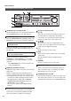
Getting Started Part Names and Functions (Front Panel) 5 6 7 OPEN/CLOSE SPLIT OPERATE REC WARNING REW ALARM 1 SET SEQUENCE FF HDD SPOT 2 TIMER/MODE VIDEO OUT RETURN LOCK AUDIO OUT 3 SERIAL FUNCTION MENU CANCEL ALARM RESET REC/STOP PLAY STOP PLAY/PAUSE SKIP 4 1 [OPERATE] Button and Operate LED Switches the main power on or off. The LED is illuminated when the OPERATE button is set to ON.
Getting Started Part Names and Functions (Front Panel) (continued) 15 OPEN/CLOSE SPLIT OPERATE REC WARNING REW ALARM SET SEQUENCE FF 16 17 HDD SPOT TIMER/MODE VIDEO OUT 18 LOCK RETURN AUDIO OUT FUNCTION SERIAL MENU CANCEL ALARM RESET REC/STOP PLAY STOP PLAY/PAUSE SKIP 8 9 10 11 8 [HDD(DVD)/0] HDD ⇔ DVD Button and LED 12 19 14 13 14 Operations Buttons [REC/STOP] Button Press this button to switch operations between DVD and Starts and ends recording. HDD.
Getting Started Part Names and Functions (Rear Panel) 24 22 23 25 26 20 27 21 WARNING: SHOCK HAZARD -DO NOT OPEN AVIS: RISQUE DE CHOC ELECTRIQUE-NE AC IN 220V - 240V 50Hz/60Hz PAS OUVRIR 28 29 20 Power Switch Switches the power on or off. The OPERATE ON mode is automatically activated when the power is switched on. (Page 16) * Make sure the system has been set in the OPERATE OFF mode before switching off the power supply.
Getting Started Part Names and Functions (Signal I/O Terminals) WARNING: SHOCK HAZARD -DO NOT OPEN AVIS: RISQUE DE CHOC ELECTRIQUE-NE AC IN 220V - 240V 50Hz/60Hz PAS OUVRIR 1 3 2 5 4 7 9 6 8 10 12 11 1 [ALARM IN 1 to 9] Terminals 1 - 9 7 [WARNING OUT] Terminal ALARM REC is activated when signals are input to these Outputs a signal when an operation abnormality or other terminals. (Page 33) error occurs on the hard disk.
Getting Started Part Names and Functions (Signal I/O Terminals) (continued) Terminal Signal Level [ALARM IN] Remarks Make Contact Input Alarm Input [EMERGENCY] Emergency Input min.400 ms [EXT REC IN] External Record Input * Set the output impedance to 10kΩ or less [CLOCK RST IN] Make Contact Input Clock Reset Input min.
Installation and Preparation Installation and Preparation \ System Connection (When connecting 9 Cameras) Connection with up to 9 cameras is possible with VR-509’s switcher. • • • Perform recording/playback by connecting to 9 cameras. Checking recorded images at Monitor. Execution of alarm recording upon detecting alarm signals.
Installation and Preparation Turning On/Off the Power Switching the Power On Switching between OPERATE ON/OFF with the button on the front panel It is possible to switch between the operational mode (OPERATE ON) and the stand-by mode (OPERATE OFF). 1. Connect the Power Cable. • Connect using the power cable supplied to an AC 220 V - 240 V 50Hz/60Hz outlet. 2. Switch on the power switch on the rear panel. • The main power is turned on to initiate a system check. • The OPERATE LED will blink.
Installation and Preparation MENU Screen Operations Displaying the MENU Screen Changing Value Setting 1. Press the [MENU] button. 4. Change the value settings with [–/+]. • The MENU screen will be displayed. * Press the [MENU] once again to close the MENU screen. • Press [–/+] to change the values displayed on the screen. DETAIL REC INTRODUCTION SET DETAIL REC DETAIL OPERATION 2.
Installation and Preparation Setting up Areas 1. Press the [MENU] button. • Opens the menus in accordance with the instructions provided in MENU Screen Operations (page 17) in the sequence of “MENU” → “DETAIL OPERATION” → “MAINTENANCE” → “AREA SELECT”. AREA SELECT LANGUAGE TIME DISPLAY FORM TIME ZONE OFF D/M/Y Europe/Paris 2. 2. Select your desired item with [S/T], and then press [–/+] to change the value settings.
Installation and Preparation Setting the Date/Time 1. Press the [MENU] button. • Opens the menus in accordance with the instructions Adjusting the “seconds” Display with the Signal I/O Terminal provided in MENU Screen Operations (page 17) in the sequence of “MENU” → “DETAIL OPERATION” → Clock Reset signal input terminal The recorder’s clock will be reset when the relevant signal is input.
Installation and Preparation Installation Settings 1. Press the [MENU] button. CAUTION When the setting has been made for a specific number of cameras, it is only possible to amend [INTRODUCTION SET-1]. In order to amend the subsequent cameras, the [OPERATION SET] data (the F, RATE, QLY, and M.DET settings for NORMAL/REC/ALARM REC) that use [STANDARD] or [REC PATTERN 1 to 9] must be reset.
Installation and Preparation Installation Settings (continued) 6. Press the [SET] button. • The recording settings for the standard mode set on the “INTRODUCTION SET - 1” and “INTRODUCTION SET 2” screens will be automatically set, and the “INTRODUCTION SET - 3” screen will be displayed. INTRODUCTION SET-3 ALARM REC NORMAL REC F.RATE(ips) QLY F.RATE(ips) (AUTO) QLY M.DET --CAM 1 8.3 N ----CAM 2 8.3 N --CAM 3 8.3 N ----CAM 4 8.3 N --CAM 5 8.3 N ----CAM 6 8.3 N --CAM 7 8.3 N ----CAM 8 8.3 N ---CAM 9 8.
Viewing Live Camera Images Viewing Live Camera Images Switching between Display Screens The VR-509 enables images to be viewed on single screens, split screens, and sequential screens. * It is not possible to change the sequential display when the playback screen is being displayed. Automatic Single Screen Switching CH9 CH3 CH2 CH1 QUAD PICTURE Press the [SEQUENCE] button to display the 4 DIVISION screen.
Viewing Live Camera Images Changing the Layout of the Split Screens 1. Press the [MENU] button. • Opens the menus in accordance with the instructions provided in MENU Screen Operations (page 17) in the sequence of “MENU” → “LIVE PICTURE”. • The layout pattern that is set is displayed at the center of the screen. • First of all, the 4 DIV PATTERN A screen will be displayed. * The layout cannot be changed when in the playback mode. • Press the [0] button to select the black screen.
Viewing Live Camera Images Setting up monitor output SEQUENTIAL 1. Press the [MENU] button. 1. Press the [MENU] button. • The [MENU] → [DETAIL OPERATION] → [MONITOR] • The [MENU] → [DETAIL OPERATION] → [MONITOR] screens will be displayed in this sequence in accordance screens will be displayed in this sequence in accordance with the [MENU Screen Operations] explained on page 17. with the [MENU Screen Operations] explained on page 17. SEQUENCIAL MONITOR BORDER COLOR AUTO CHANGE .. SPLIT PICTURE ..
Viewing Live Camera Images SPLIT PICTURE ONSCREEN MODE Sets whether or not to display each screen with automatic switching when in the split picture mode. Sets whether or not each of the settings are to be displayed during the ONSCREEN mode. 1. Press the [MENU] button. 1. Press the [MENU] button.
Viewing Live Camera Images Viewing Live Images with SPOT Output It is possible to view live images with the SPOT output function. The following two methods for changing the display contents for SPOT output are available: Changing SPOT Output with Terminal Input on the Rear Panel Make up the [SPOT1] and [SPOT2] terminals on the rear panel for 400 ms or more. • The setup screen will change to SPOT output when the • Changing SPOT output manually. SPOT1 and SPOT2 terminals are input.
Viewing Live Camera Images COVERT CHANNEL COVERT CHANNEL (WEB) Sets whether or not the screen is to be displayed in black Sets whether or not the screen is to be displayed in black without the camera inputs being displayed. without the camera inputs being displayed when watching live images on a personal computer. 1. Press the [MENU] button.
Recording Camera Images Recording Camera Images Types of Recording Alarm Recording Normal Recording The normal recording mode is operated as follows in Alarm recording is started when signals are input or motion is accordance with the [TIMER/MODE (REC PATTERN)] setting detected in the pause mode, and during normal recording and made on the [DETAIL REC] screen (See page 30), and the ON/ timer recording. OFF setting for the [TIMER/MODE].
Recording Camera Images Making Normal Recording with the EXT REC I/O Terminals Making Normal Recordings STANDARD MODE Enables the start and stop operations when recording to be controlled by signals input to the [EXT REC IN] terminal on the 1. Set up the DETAIL REC parameters. (See page 30) rear panel, instead of the [REC/STOP] button. 2. Set the normal recording parameters with [STANDARD MODE]. (See page 31) 1. Set the [EXT REC IN] setting to [TRIGGER] or [MANUAL]. (See page 49) 3.
Recording Camera Images Setting up the DETAIL REC 1. Press the [MENU] button. PASSCODE ERROR REC • Opens the menus in accordance with the instructions provided in MENU Screen Operations (page 17) in the sequence of “MENU” → “DETAIL REC”. illegal passcode has been detected. Recording will be started with the same settings as [EMERGENCY] recording. However, it is not possible to forcibly stop recording by pressing DETAIL REC OPERATION SET .. NOMALLY AUDIO REC ALARM AUDIO REC ALARM TERMINAL .. ALARM REC .
Recording Camera Images Setting the Operation Set 1. Press the [MENU] button. • Opens the menus in accordance with the instructions provided in MENU Screen Operations (page 17) in the sequence of “MENU” → “DETAIL OPERATION” → “OPERATION SET”. 4. Select “ALARM REC” with [S/T/W/X], and then select “QTY” “F.RATE” or “M.DET” with [–/+]. Settings F.RATE OPERATION SET STANDARD .. REC PATTERN1 .. REC PATTERN2 .. REC PATTERN3 .. REC PATTERN4 .. REC PATTERN5 .. REC PATTERN6 .. REC PATTERN7 .. REC PATTERN8 ..
Recording Camera Images Setting the Operation Set (continued) Procedure for Changing the Number of Cameras 1. Take a note of all the [OPERATION SET] data settings Operation Setup (RECOVERY REC, REC INDICATOR, REPEAT REC) 1. Press the [MENU] button. • The [MENU] → [DETAIL OPERATION] → [OPERATION (F.RATE, QLY and M.DET on NORMAL REC/ALARM SET] → [OPERATION] screens will be displayed in this REC) when [STANDARD] or [REC PATTERN 1 to 9] is sequence in accordance with the [MENU Screen in use.
Recording Camera Images ALARM Recording Alarm recording is started when signals are input and when motion is detected in the STOP mode, and during normal recording and timer recording. Setting up the ALARM TERMINAL 1. Press the [MENU] button. • The [MENU] → [REC DETAIL] → [ALARM TERMINAL] screens will be displayed in this sequence in accordance with the [MENU Screen Operations] explained on page 17. Emergency Recording ALARM TERMINAL 1. Connect the [EMERGENCY] terminal to the alarm device.
Recording Camera Images Setting ALARM Recording Ending ALARM Recording 1. Press the [MENU] button. Alarm recording is stopped when [ALARM RESET] is pressed • The [MENU] → [REC DETAIL] → [ALARM REC] screens will be displayed in this sequence in accordance with the [MENU Screen Operations] explained on page 17. during alarm recording (signal input terminal, motion detection.
Recording Camera Images Using the Motion Detection Function There are two methods of performing motion detection: 1) with Dynamic Sensitivity Level: a pre-determined set of parameters, and 2) by freely setting The level value for detection. The higher the value, detection sensitivity. It is also possible to set the area for which detection is to be carried out on the screen. the higher the sensitivity (1 to 10).
Recording Camera Images Motion Detection with Freely Determined Sensitivity Levels When the [Motion Detection] value on the [OPERATION SET] Manual Setup screen is set at [USER], it is possible to set the sensitivity for [DYNAMIC SENSITIVITY LEVEL], [TARGET AREA LEVEL] Use the manual settings if the desired level of detection is not and [STOP LEVEL]. These settings have no effect if anything attained with STANDARD or OTHER SCENE. These three other than [USER] has been specified.
Recording Camera Images Setting up the MOTION DETECT AREA SET Sets up the area for motion detection. This setting is applicable for when both [USER] and any other parameter has been selected for the sensitivity level. 1. Press the [MENU] button. • The [MENU] → [REC DETAIL] → [ALARM REC] screens will be displayed in this sequence in accordance with the [MENU Screen Operations] explained on page 17.
Recording Camera Images WEEKLY TIMER 1. Press the [MENU] button. “END” Time • Opens the menus in accordance with the instructions 00:00 to 23:59: Sets the time at which recording is to end. provided in MENU Screen Operations (page 17) in the sequence of “MENU” → “DETAIL REC” → “WEEKLY STANDARD, REC PATTERN 1 to REC PATTERN 9: Selects the appropriate setting from among multiple recording settings. (See OPERATION SET on page 31) TIMER”. 2. 3. 4. 5. 6.
Recording Camera Images DATE TIMER 1. Press the [MENU] button. • Opens the menus in accordance with the instructions provided in MENU Screen Operations (page 17) in the sequence of “MENU” → “DETAIL REC” → “DATE TIMER”. 2. 3. 4. DATE TIMER START **:** 1. 2. 3. 4. 5. 6. 7. 8. END **:** MODE **** **/** **/** **/** **/** **/** **/** **/** **/** 9. 10. 11. 12. 13. 14. 15. 16. **/** **/** **/** **/** **/** **/** **/** **/** EXEC ** 5. 6. 8. Select [SAVE] with [W/X], and then press the [SET] button.
Playing Back Recorded Images Playing Back Recorded Images Playing Back during Recording (Simultaneous Playback Mode) Playing Back Images Plays back recorded images. This is activated by running a search according to the date of the image to be played back using “SEARCH DATE” (See page 43) or in accordance with the time when alarm signals are received using the “ALARM LIST SEARCH” feature. (See page 42) It is possible to view recorded images when in the Recording mode.
Playing Back Recorded Images Switching between Playback Screens The VR-509 is equipped with features to playback images on single screens and split screens. * Sequential display is not possible during playback. 4 DIVISION SCREEN Single Screen [SPLIT] CH1-9 [SPLIT] [1] - [9] [1] [2] CH1 CH2 CH5 CH6 CH3 CH4 CH7 CH8 [3] 4. Press [5] to display the 9 DIV PATTERN screen.
Playing Back Recorded Images Searching with the Alarm List 1. Press the [PLAY/PAUSE] button. TYPE • The “EVENT SEARCH” screen will be displayed. EVENT SERCH CONTINUOUS PLAYBACK ALARM LIST SEARCH .. SEARCH DATE **/**/20** **:** SKIP SET .. Play with PLAY / PAUSE button. 2. SKIP Emergency recording, Passcode error recording. Alarm recording with the signal input terminal. Alarm recording with motion detection. Emergency recording, passcode error recording and all alarm recordings.
Playing Back Recorded Images Searching for Images According to Date/ Time 1. Press the [PLAY/PAUSE] button. • The “EVENT SEARCH” screen will be displayed. Playback speed can be adjusted by turning the jog/shuttle dial. This feature is very useful when searching for a specific screen for viewing. Rotating the Shuttle Dial EVENT SERCH CONTINUOUS PLAYBACK ALARM LIST SEARCH .. SEARCH DATE **/**/20** **:** SKIP SET .. Play with PLAY / PAUSE button. Adjusting Playback Speed (Jog/Shuttle Playback) 2.3.
Playing Back Recorded Images Skipping Recorded Images 1. Press the [PLAY/PAUSE] button. • The “EVENT SEARCH” screen will be displayed. 4. Press the [SET] button. • A confirmation screen will be displayed. EVENT SERCH 5. Select [SAVE] with [W/X], and then press the [SET] CONTINUOUS PLAYBACK ALARM LIST SEARCH .. SEARCH DATE **/**/20** **:** SKIP SET .. Play with PLAY / PAUSE button. button. 2. 6. Press [RETURN] to return to the [EVENT SEARCH] SKIP OLDEST EVENT screen. LATEST EVENT 7.
Playing Back Recorded Images Enlarging Images (Image Zoom) AUDIO OUT Images can be viewed in an enlarged mode. Only single-screen displays can be enlarged. * Enlarged displays are not possible when live images are being displayed. Sets whether to link the AUDIO 1 or 2 to a specified input or not. 1. Start playback (See page 40 “Playing Back Images”) 1. Press the [MENU] button. 2. Press buttons [1] to [9] to select the camera input that is to be enlarged.
Useful Features Using a PC Useful Features Using a PC Changing the Onscreen Display Position As can be seen in the illustrations below, the VR-509’s DATE/ TIME, camera title and other elements can be displayed on the TITLE monitor screen. It is also possible to change their position on the screen. Set the display mode to live images on a single screen. DATE/TIME CAP. / MODE (DVD MODE) AL DET. EAL No.
Useful Features Using a PC Setting Camera Title 1. Press the [MENU] button. • Opens the menus in accordance with the instructions provided in Changing MENU Settings (page 17) in the sequence of “MENU” → “DETAIL OPERATION” → Deleting Characters • To delete a character from the title, align the cursor with the relevant character and press the [CANCEL] button. “MONITOR” → “CAMERA TITLE”. 6. Press the [SEQUENCE] button after the camera title CAMERA TITLE has been entered.
Useful Features Using a PC Setting OPERATION LOCK Table 4: Buttons to be prohibited (REC STOP, ALL) 1. Press the [MENU] button. • Opens the menus in accordance with the instructions provided in Changing MENU Settings (page 17) in the Front Button REC STOP ALL OFF OFF ON OFF [MENU] OFF OFF [FUNCTION] ON OFF ON OFF OFF OFF ON OFF OFF OFF sequence of “MENU” → “DETAIL OPERATION” → [REC] “ONSCREEN/OPERATION” → “OPERATION”.
Useful Features Using a PC Buzzer Setup REAR TERMINAL 1. Press the [MENU] button. 1. Press the [MENU] button. • The [MENU] → [DETAIL OPERATION] → [Display/ • The [MENU] → [DETAIL OPERATION] → [Display/ Operation] → [BUZZER] screens will be displayed in this Operation] → [REAR TERMINAL] screens will be sequence in accordance with the [MENU Screen displayed in this sequence in accordance with the Operations] explained on page 17. [MENU Screen Operations] explained on page 17.
Useful Features Using a PC Hard Disk Maintenance MANUAL SCAN DISK When a power failure occurs while in the Recording mode or Performs manual scanning of the hard disk. Perform Manual Alarm Record Standby mode, or when a failure occurs in the Scan Disk regularly when the “AUTO SCAN DISK” item in the recorded data on the hard disk, recording/playback may not menu is set to “OFF” or when the power to the equipment function properly.
Useful Features Using a PC DEFRAG DATABASE Initializing the Hard Disk (“FORMAT”) When alarm recording is performed repeatedly with Repeat Recording may fail if there is insufficient space on the hard disk. Recording set to “ALL” or “ALARM LOCK”, data in the hard disk When there is insufficient hard disk space, create a backup may become fragmented. Continued use of such data may data and format the disk to create space for the recorded data.
Useful Features Using a PC Setting up the Hard Disk for Mirroring Mirroring refers to recording the same data in the 2 built-in hard disks. In this way, recorded data can be secured even if data on one of the hard disks is damaged. Canceling MIRRORING 1. Press the [MENU] button.
Useful Features Using a PC Setting up the Hard Disk for Mirroring (continued) Deleting Alarm Lists It is possible to delete only the alarm lists without disturbing the Precautions When Setting up Mirroring • The capacity of the hard disk will be reduced by alarm recorded images. 1. Press the [MENU] button. • The [MENU] → [DETAIL OPERATION] → approximately half when mirroring is set up. It is therefore • • necessary to take care when setting recording times.
Useful Features Using a PC Displaying the Power Outage Time List and Log Pass Code Setup 1. Press the [MENU] button. • The [MENU] → [DETAIL OPERATION] → [MAINTENANCE] → [PASSCODE SET] screens will be displayed in this sequence in accordance with the [MENU Screen Operations] explained on page 17. 1. Press the [MENU] button. • The [MENU] → [DETAIL OPERATION] → [MAINTENANCE] → [MAINTENANCE/LOG] screens will be displayed in this sequence in accordance with the [MENU Screen Operations] explained on page 17.
Useful Features Using a PC Hard Disk Recovery Feature Rebooting the System • 1. Press the [MENU] button. abnormalities on the hard disk when it is automatically • The [MENU] → [DETAIL OPERATION] → rebooted.
Using DVD Using DVD DVD for Recording & Playback The following shows the discs that can be recorded to and played using VR-509, in addition to the corresponding display marks or logos. Inserting & Removing DVD Inserting a DVD 1. Press the [OPEN/CLOSE] button. DVD-R • The disc tray will open automatically. 12 cm: 4.7 GB General Version 2.0 (video mode) 2. Place the disc on the disc tray. • Ensure that the disc is inserted correctly into the tray’s DVD-RW 12 cm: 4.
Using DVD Exporting Data on DVD The VR-509 is equipped with a function to enable the images stored on the hard disk to be exported to DVDs. * It is possible to export images to a DVD when recording onto the hard disk. 1. Press the [HDD(DVD)] button. • The display LED will be illuminated, and the DVD operation mode will be activated. * It is not possible to switch across to the DVD operation mode during HDD playback. 2. Press the [MENU] button. • The “DVD” screen will be displayed.
Using DVD Exporting Data on DVD (continued) 6. Setting up the [DURATION] setup screen.
Using DVD Exporting Data on DVD (continued) Displays During DVD Export The status of execution will be displayed on the live screen Points to Note During DVD Export • when the DVD export process is in progress. D.S: Searching for the relevant file. D.E: Deleting the data that has been written onto the DVD. D.C: Converting the data into a format that conforms with the DVD-Video format. D.W: Writing the converted files onto the DVD. D.F: • • • Performing the finalization process.
Using DVD Playing Back Exported Images on DVD It is possible to playback the images that have been exported from the hard disk to DVDs. Set the export format to format including “SELF-PLAYING” when exporting the data. * DVD images can be played back when recording onto the HDD. 5. Select the chapter that is to be played back with the [S/T] keys, and then press the [PLAY/PAUSE] button. • Playback will be carried out continuously in sequence from the selected chapter.
Using DVD DVD-Video Format Menus and Playback The following title menus and chapter menus are created for DVDs that are formatted in the DVD-Video and DVD-Video Chapter Menus (intermittent interpolation) formats for exporting purposes. * DVDs that are created in the DVD-Video and DVD-Video 01. 2005/10/01 10:01:00 - 2005/10/01 10:05:59 N (intermittent interpolation) cannot be played back on the VR509E. 02.
Using Other External Devices Using Other External Devices Capturing Still Images on the Flash Memory It is possible to capture still images onto USB flash memories when in the playback mode. 1. Connect a USB flash memory to the [SERIAL] port on the front or back panel. 2. Set the VR-509 in the playback mode. (See page 40) 3. Press the [PLAY/PAUSE] button when the image that is to be captured is displayed to pause playback. 4.
Using Other External Devices Storing Set Data in the Flash Memory 1. Connect the flash memory to the [SERIAL] port on the front or on the back panel. 4. Select [EXEC] on the confirmation screen, and then press the [SET] button. 2. Press the [MENU] button. • Open the menus in accordance with the instructions provided in Changing MENU Settings (page 17) in the sequence of “MENU” → “DETAIL OPERATION” → “MAINTENANCE”→“MAINTENANCE/LOG”.
Using Other External Devices External Hard Disk Drives Connecting a UPS The VR-509 allows connection of one external hard disk drives UPS: Uninterruptible Power Supply in addition to the 2 built-in hard disks. Follow the procedure Connecting a UPS to the hard disk will protect it from damage below to alter the connection setup of the hard disk. There are by automatically powering down all operations prior to 3 ways of altering connection setup, namely “NEW”, switching off the power supply.
Connecting to a PC Connecting to a PC You Can Do the Following Connecting Using a LAN Cable z Viewing Live Images Using a PC (Page 69) z Record Program Using a PC (Page 70) z Viewing Playback Image Using a PC (Page 73) z Useful Functions Using a PC (Page 76) Connecting the Network (LAN) • Connect the PC to the hub and the VR-509 to the hub with the use of straight LAN cables.
Connecting to a PC Setting up a Network for VR-509 Perform the initial setup procedure for the VR-509 while referring to the connected monitor screen. 6. Press the [SET] button. • The settings will be saved. 1. Press the [MENU] button. • When a DHCP server has been set for METHOD, the IP • Opens the menus in accordance with the instructions provided in Changing MENU Settings (page 17) in the sequence of “MENU” → “DETAIL OPERATION” → “NETWORK”.
Connecting to a PC Setting up a PC Network The following illustrates how to set up a small LAN using VR509’s factory settings. 1. Click on the button. 5. 6. 7. 8. • Right-click on [My Network], and then select the “Properties”. 2. Select the network that is connected to the PC that operates the Web browser. • Right-click on “Properties”. 9. 5. Select “Use the following address” 6. Set the “IP Address” to 192.168.0.11 7. Set the “Subnet Mask” to 255.255.255.0 3. Confirm that this field is ticked. 8.
Connecting to a PC Connecting (Login) to the Network • The Live Image window and the top page will be 1. Start up the Web browser. displayed if login is successful. Top Page 1. 2. 3. ,, 2. Click on Go. ,, 2. Enter http://192.168.0.10 2. Enter the VR-509 IP address (default factory setting: 191.168.0.10) in the “Go”. 4. field, and then click on 1. Displays the title. 2. Displays the selection menu. 3. Displays the setup screen. 4. The contents of each of the selection menu will be 3.
Viewing Live Images Using a PC Viewing Live Images Using a PC Live Image Display 1. Click on the Live Images button. • The Live Images display window will be displayed. 1. 2. 3. 4. 5. 6. 7. 8. 9. 10. 1. Live Image Display Area 8. [PC REG./DEL] Click on this button to save the live image display window settings onto the personal computer, and to delete the live image display window settings from the personal computer. The [PC REGISTER/DELETE] screen will be displayed.
Record Program Using a PC Record Program Using a PC Adding to the Weekly Timer Changing and Deleting the Weekly Timer 1. Click on [TIMER RECORDING] → [WEEKLY TIMER]. • The [WEEKLY TIMER SETUP] and program list (weekly timer settings) screen will be displayed. 1. Click on [TIMER RECORDING] → [WEEKLY TIMER]. • The [WEEKLY TIMER SETUP] and program list (weekly timer settings) screen will be displayed. 2. 3. 2. 4. 5. 6. 7. 2. Select the [PROGRAM] number against which recording is to be reserved. 3.
Record Program Using a PC Adding to the Date Timer Deleting the Date Timer 1. Click on [TIMER RECORDING] → [DATE TIMER]. • The [DATE TIMER SETUP] and program list (date timer settings) screen will be displayed. 1. Click on [TIMER RECORDING] → [DATE TIMER]. • The [DATE TIMER SETUP] and program list (date timer settings) screen will be displayed. 2. 3. 2. 4. 5. 6. 7. 2. Select the [PROGRAM] number against which recording is to be reserved. 3. Select the [DATE (DD:MM)] for the recording. 4.
Record Program Using a PC TIMER MODE When the TIMER MODE is Deactivated 1. Click on “TIMER RECORDING” → “TIMER MODE” in that order. 2. 2. Click the [ON] button. • The TIMER MODE will be activated. When the TIMER MODE is Activated 1. Click on “TIMER RECORDING” → “TIMER MODE” in that order. 2. 2. Click on the [OFF] button. • The TIMER MODE will be deactivated.
Viewing Playback Image Using a PC Viewing Playback Image Using a PC ALARM SEARCH 1. Click on “EVENT SEARCH” → “ALARM SEARCH” in ALARM SEARCH Screen that order. 5. 2. 6. 7. 3. 2. Select the search conditions. Settings ALARM CHANNEL All Alarm Channels: Searches for all recorded images regardless of the channel. ch1 to ch9: Searches for recorded images only on the specified channel. DETECTION All: Searches for all recorded images regardless of the alarm type.
Viewing Playback Image Using a PC TIME/DATE SEARCH 1. Click on “EVENT SEARCH” → “TIME/DATE SEARCH” in that order. 2. 3. 4. 2. Enter the date and time of the search. 3. Select the channel to be searched. 4. Click on the [SEARCH] button. • Playback screen will be displayed. (Click on the RESET button to clear the entry.
Viewing Playback Image Using a PC Playback Image Display 1. Executes either the “ALARM SEARCH” or the “TIME/DATE SEARCH”. • The Playback image display screen will be displayed. 2. 1. 3. 4. 5. 6. 7. 1. Live Image Display Area Displays live images. CAUTION • 2. [REC TYPE] Displays the recording mode. NORMAL, TIMER, ALARM, etc. • 3. [STATUS] Displays the playback status. TOP, END, -x5, ..., -x1, PAUSE, x1, ..., x5 4. [PIC SIZE (%)] Selects the size of the display.
Useful Functions Using a PC Inputting a Camera Title 1. Click on “DISPLAY” → “CAMERA TITLE” in that order. Useful Functions Using a PC Covert Channel Setting for Live image/ Playback display screen 1. Click on “WEB” → “COVERT CHANNEL” in that order. 2. 3. 4. * When [CAM1 to CAM9] for the [INPUT NO.] is grayed out, 2. it indicates that the camera input setting for [INTRODUCTION SET-1] is set at [DISCONNECT]. (See page 20) CAUTION 3.
Useful Functions Using a PC Mail Notification Setting During Alarm Input 1. Click on “NETWORK” → “E-MAIL” in that order. 3. Check the existing network settings. Display Items DOMAIN NAME Displays the domain name. 2. DNS SERVER Displays the DNS server. 4. Click on the [SAVE] button. • An e-mail will be transmitted in accordance with the 3. specified parameters when an alarm is input. 4. 5. The mail sending report settings confirmation screen 2. Enter/Select the required parameter. will be displayed.
Useful Functions Using a PC Adjusting Clocks with the NTP Server If the times set in the system clocks of all VR-509 that are linked Canceling NTP Server Registration 1. Click on “NETWORK” → “NTP SERVER” in that order. up to a multiple unit network are not synchronized, alarm searches cannot be performed accurately. It is therefore necessary to make sure that all system clocks are synchronized in accordance with the NTP server settings when 2. multiple VR-509s are connected together. 3. 2.
Useful Functions Using a PC Downloading VR-509 Settings 1. Click on “UTILITY” → “DOWNLOAD” in that order. 2. 2. Click on the [EXEC] button. • The “DOWNLOAD IN PROGRESS” screen will be displayed. • A screen stating “Download data making completion” will be displayed when the download has finished. 3. 3. Click on the [SAVE] button. • The “FILE DOWNLOAD” screen will be displayed. 4. 4. Click on the [SAVE] button. • The “SAVE AS” screen will be displayed. 5. 5. Click on the [SAVE] button.
Useful Functions Using a PC Uploading VR-509 Settings 1. Click on “UTILITY” → “UPLOAD” in that order. 7. Click on the [EXEC] button. • The uploading procedure will be activated. 2. 8. Wait until the upload procedure has been completed. • A screen stating “UPLOAD COMPLETE” will be displayed when the uploading procedure has finished. • VR-509 will be automatically restarted. 2. Click on the [Browse] button. • The “FILE SELECTION” screen will be displayed. 3. 4. 3.
Useful Functions Using a PC MAINTENANCE 1. Click on “UTILITY” → “MAITENANCE” in that order. STATUS 1. Click on “STATUS”. • Displays the usage time and power outage time list. OPERATION LOG 1. Click on “UTILITY” → “OPERATION LOG” in that order. • Displays the OPERATION LOG. • Displayed in the sequence of date/time the operation log was saved, date/time the operation was carried out, and the contents of the operation. RECORDING LOG 1. Click on “UTILITY” → “RECORDING LOG’ in that order.
Changing Network Settings Changing Network Settings 0 Setting a Network Address 1. Click on “NETWORK” → “ADDRESS” in that order. Access rights for each menu: Administrators Operators Users Live Image Screens 2. 3. 2. Change the settings. (For more details, see page 66) • When network settings of VR-509 are changed, network settings need to be altered according at the PC. Consult the network administrator when making alterations.
Changing VR-509 Settings Using a PC Changing VR-509 Settings Using a PC It is possible to change the VR-509 settings with the use of a personal computer. See the reference page for further details of the relevant parameters. AUTO CHANGE MONITOR OUT 1. Click on “DISPLAY” → “MONITOR OUT” in that order. 1. Click on “DISPLAY” → “AUTO CHANGE” in that order. 2. 2. 3. 2. Change the settings. (See page 24 for details) 3. Click on the [SAVE] button. 3.
Changing VR-509 Settings Using a PC COVERT CHANNEL REC PATTERN 1. Click on “DISPLAY” → “COVERT CHANNEL” in that order. It is possible to change the default recording parameters for each mode on the same screen as the setup mode selection screen. 1. Click on “FUNCTION” → “REC PATTERN” in that order. 2. 2. 3. 3. 2. Change the settings. (See page 27 for details) 3. Click on the [SAVE] button. (Click on the [RESET] button to return to the setting values 4. on the main unit.) 2.
Changing VR-509 Settings Using a PC OPERATION 1. Click on “FUNCTION” → “MOVEMENT SETUP” in that order. • If a check mark is added to the number that denotes the camera input to the right of a alarm terminal that has received an input, it means it has been enabled. If it remains blank, it means it is disabled. 3. Click on the [SAVE] button. 2. 3. 2. Change the settings. (See page 32 for details) 3. Click on the [SAVE] button.
Explanations Explanations Menu Flowchart LIVE PICTURE INTRODUCTION SET DETAIL REC DETAIL OPERATION LIVE PICTURE 4DIVISION-A Button operation explanation SET UP CURSOR UPDATE/NEXT BACK FUNCTION : USER GUIDANCE (Page 18) (Page 23) INTRDUCTION SET-1 INTRODUCTION SET-2 CONNECT CONNECT CONNECT CONNECT CONNECT CONNECT CONNECT CONNECT CONNECT SMOOTH CAM 1 CAM 2 CAM 3 CAM 4 CAM 5 CAM 6 CAM 7 CAM 8 CAM 9 PRIORITY DURATION AUDIO REC REPEAT REC 5 DAYS ON ALL (Page 20) (Page 20) DETAIL REC OPERATION SET
Explanations Menu Flowchart (continued) INTRODUCTION SET-3 UCTION SET-2 5 DAYS ON ALL ALARM REC NORMAL REC F.RATE(ips) QLY F.RATE(ips) (AUTO) QLY M.DET --CAM 1 8.3 N ----CAM 2 8.3 N --CAM 3 8.3 N ----CAM 4 8.3 N --CAM 5 8.3 N ----CAM 6 8.3 N --CAM 7 8.3 N ----CAM 8 8.3 N ---CAM 9 8.
Explanations Menu Flowchart (continued) MONITOR INTRODUCTION SET DETAIL REC DETAIL OPERATION LIVE PICTURE Button operation explanation SET UP CURSOR UPDATE/NEXT BACK FUNCTION : USER GUIDANCE BORDER COLOR AUTO CHANGE .. SPLIT PICTURE .. COVERT CHANNEL .. CAMERA TITLE ..
Explanations Menu Flowchart (continued) SPLIT PICTURE 1 SEC 1 SEC 1 SEC 1 SEC 1 SEC 1 SEC 1 SEC 1 SEC 1 SEC 1 SEC 4 DIVISION 4 DIVISION-A 4 DIVISION-B 4 DIVISION-C COVERT CHANNEL ENABLE ENABLE ENABLE (Page 24) CAMERA TITLE DISABLE CAMERA 1 DISABLE CAMERA 2 DISABLE CAMERA 3 DISABLE CAMERA 4 DISABLE CAMERA 5 DISABLE CAMERA 6 DISABLE CAMERA 7 DISABLE CAMERA 8 DISABLE CAMERA 9 SPOT+MONITOR OUT SELECT COVERT OFF PLAY PERMISSION COVERT CHANNEL (WEB) ..
Explanations Menu List [z] are factory settings.
Explanations Menu List (continued) [z] are factory settings.
Explanations Menu List (continued) [z] are factory settings.
Explanations Menu List (continued) [z] are factory settings.
Explanations Menu List (continued) [z] are factory settings. REAR TERMINAL (Page 49) Items Settings EXT REC z OFF, TRIGGER, MANUAL REC OUT z OFF, ALL, ALARM REC, STOP REC WARNING OUT z OFF, USER, ALL VIDEO LOSS ON, z OFF HDD ERROR ON, z OFF FAN MOTOR ERROR ON, z OFF PASSCODE ERROR ON, z OFF BLACKOUT ERROR ON, z OFF NETWORK (Page 66) Items Settings HOST NAME z vr509 METHOD OFF, z STATIC IP, DHCP IP ADDRESS z 192.168.0.10 NET MASK z 255.255.255.0 DEFAULT GATEWAY z 192.168.0.
Explanations Menu List (continued) [z] are factory settings.
Explanations Troubleshooting Problems Related to Error Code and Onscreen Display Onscreen Display “E-01 DETECTED.” *1, *2 Cause and Recovery • System restarted due to error in the functioning of the hard disk. • Continues operation with the intact hard disk. • The data in the disconnected hard disk will not be recovered if the manual scan disk is executed. Refer to Page – → Switch the power supply off and then on again, and try the formatting or defrag functions once again.
Explanations Troubleshooting (continued) Problems Related to Error Code and Onscreen Display (continued) Onscreen Display Cause and Recovery Refer to Page “HARD-DISK CAPACITY IS VERY • LITTLE” → When hard disk space is about to run out, make changes accordingly Recordable space on the hard disk is running out. P51 such as formatting the hard disk or changing the setting to the Repeat P32 Record mode. * All event record data will be deleted when formatting is executed.
Explanations Troubleshooting (continued) Problems with the DVD If the following messages are displayed during DVD exporting or DVD playback, press the [CANCEL] button to delete the message, and then check the cause of the problem. Onscreen Display Cause and Recovery “DVD export data retrieval was discontinued (D-01)” “DVD export data retrieval was discontinued (D-02)” “DVD export data retrieval was discontinued (D-03)” • No relevant retrieval data.
Explanations Troubleshooting (continued) Other Problems Onscreen Display Cause and Recovery Refer to Page Power cannot be turned on. → Check to ascertain that the power cable has been plugged in correctly. [REC] and [PLAY] buttons do → Check to ascertain if the OPERATION LOCK is activated. not work. → Check to ascertain if the TIMER STANDBY mode is activated. Playback image is not → Check the monitor connection. P15 displayed on the monitor. → Select a camera that has a recorded image.
Explanations Troubleshooting (Web Browser) Problems that Trigger Error Messages Error Message Cause and Recovery [Normal Recording in Progress: (5XX2)] [Timer Recording in Progress: (5XX3)] [Alarm Recording in Progress: (5XX5)] Perform operations via the Web browser after stopping or ending all [Emergency Recording: (5XX6)] operations on the VR-509.
Explanations Troubleshooting (Web Browser) (continued) Problems that Trigger Error Messages Error Message Unable to gain access by entering the specified URL at the browser. User name and password are requested when “CONFIGURATION” and “TIMER RECORDING” Cause and Recovery → Disable the use of proxy servers in the “Internet Options” Menu of the Web browser. → Login by entering a registered user name and password with a higher level of access rights. are selected.
Explanations Web Browser Glossary Domain name The network name to which the network-connected PC belongs. Host Name Name of PC (or VR-509) on the network. The name of the PC connected to the network is managed by a database called DNS (Domain Name System). DNS links the IP address assigned to each PC with the domain names, and enables a user to specify a PC to access. IP Address An identification number assigned to each PC connected to the network.
Explanations Normal Recording Beginning of hard disk Event1 Record • End of hard disk Event2 Record Event3 Record Event4 Record Recording is executed from the start till the end of the hard disk during normal recording. • A recording operation from the time it starts till it ends is referred to as an “Event”. • Recording will stop when it reaches the end of the hard disk, and further recording will not be possible.
Explanations Repeat Recording When recording reaches the end of the hard disk and there is no space left for recording, it returns to the start of the hard disk When “ALL” is selected • Execute repeat recording regardless of alarm recording/ to overwrite old data. Such an operation is known as Repeat normal recording area. Record. Display the “OPERATION” in MENU Screen • Recording will continue lastingly until stopping the Operations to execute Repeat Rec mode. (Page 32) recording.
Explanations Prealarm Recording Prealarm Recording is a feature that works hand-in-hand with Alarm Recording that starts recording automatically by tracing back to the time prior to the input of alarm signals. Notes On Prealarm Rec • Display the “OPERATION” in MENU Screen Operations to selected, the display will jump to the starting position of the execute PREALARM REC or PREALARM TIME. (Page 34) pre-alarm recordings during the alarm search.
Explanations Skip jump There are 3 types of Skip Jump, namely “TIME”, “ALARM” and “EVENT”, which can be specified in the search menu. Display the “SKIP MODE” in SKIP PLAY to execute SKIP button When “EVENT” is selected • Pressing [SKIP] each time enables a jump to the start position of recording (start of an event). setting.
Explanations Using the NTP Server Function The NTP Server function is enabled in accordance with the following procedure with Windows XP. 1. Click on [START] and then click on [Run...] Enter the “regedit” command and then click [OK]. 2. Set the following registry value to [5]. HKEY_LOCAL_MACHINE\SYSTEM\CurrentControlSet\ Services\W32Time\Config\AnnounceFlags 3. Set the following registry value to [1].
Explanations Activating ActiveX Control and Plug-ins Follow the procedures explained below to activate ActiveX Control and plug-ins with Internet Explorer if they are not already activated. Starting up Internet Explorer Select [Tools] → [Internet Options] → [Security], and then click on [Trusted Sites]. This will enable the [Trusted Sites [Site...]] window to be opened. Click on this to open the [Trusted Sites] window.
Explanations Notes Related to Summer Time The VR-509 makes use of Time Zone to perform automatic switching for Summer Time and Winter Time. * The starting/ending time of Summer Time may differ from the actual time in your local area. 1. Changing the Time Zone After changing the Time Zone during operations, make sure to format all the hard disks. If the hard disk is not formatted after changing the Time Zone, the following problems will arise.
Explanations Recording Duration Actual recording duration varies according to the input image as well as hard disk conditions. The table below is an example of detailed images (eg. in a convenience store) that illustrates the recording duration based on different modes of recording quality. Refer to the following table when recording detailed images.
Explanations Recording Duration (continued) Requirements: Upon setup of standard HDD (320 GB) (2/2) Repeat Rec off / Audio off Total Framerate Total Framerate SMOOTH HIGH-QUALITY SMOOTH HIGH-QUALITY Total Framerate Total Framerate SMOOTH HIGH-QUALITY SMOOTH HIGH-QUALITY SMOOTH HIGH-QUALITY SMOOTH HIGH-QUALITY Repeat Rec off / Audio on Total Framerate Total Framerate SMOOTH HIGH-QUALITY SMOOTH HIGH-QUALITY Total Framerate Total Framerate * Recording duration may shorten by about 10%
Explanations DVD Recording Time The following charts provide guidelines to the recording time for one channel that can be recorded onto a single DVD. The charts are listed by export format. The conditions for all of these are as follows: Tie Date Recording: No Audio: Yes (however, audio will not be recorded for 0.2ips or 0.08ips.) The following charts have been created under the assumption that only one channel will be used.
Explanations Time Required for DVD Exporting The following chart provides guidelines to the amount of time required for exporting one hour’s worth of recorded data for a single channel in the self-playing + DVD-Video (OPT) format. Note that the exporting times are merely estimates, and the actual times may differ greatly depending on the DVD media in use, and the status of the VR-509. Framerate High 30fps 15fps 10fps 6fps 3fps 2fps 1fps 0.5fps 0.2fps 0.
RS-232C Interface RS-232C Interface 1. Electrical Specifications 1. D-Sub 9-pin Connector Specifications Pin No. Signal Operations Signal Direction 3 TXD Sending data HDR → CPU 2 RXD Receiving data HDR ← CPU 6 DSR Data set ready HDR ← CPU 5 GND Signal earth 4 DTR Data terminal ready Output level OFF: —5V or less ON : +5V or more 12345 HDR → CPU 6 9 2.
RS-232C Interface 2.
RS-232C Interface 3. Details of the Commands The numbers within parenthesis indicate the corresponding table. 3.1. RETURN CODE • ERROR (02H) [BASIC/JVC-1] • The ERROR is returned when the VR-509E receives an un-receivable command related to a series of commands. This command will not be accepted when sent, and only the status SENS command will be returned (the status SENS command is also valid in error modes, and is returned.) Enter the CLEAR ERROR (41H) or CLEAR (56H) commands to clear this mode.
RS-232C Interface 3. Details of the Commands (continued) 3.2. Operation Commands (continued) • TD SEARCH(92H) [JVC-1] • The command to queue up data in the specified date location. The date is specified by month, day, year, hour and minute in a numerical command with ten characters.
RS-232C Interface 3. Details of the Commands (continued) 3.3. Setup Commands • • • • DOWN (63H) [JVC-1] RIGHT (64H) [JVC-1] LEFT (68H) [JVC-1] UP (69H) [JVC-1] Shifts the parameter settings when the timer PRG and the alarm search parameters have been set. Shifts the selection fields with the [UP] and [DOWN] keys when the menu is being displayed. • SEQ (6AH) [JVC-1] Changes the monitor output screen mode. • MENU ON (6BH) [JVC-1] Displays the menu.
RS-232C Interface 3. Details of the Commands (continued) 3.4. SENS Commands • ROM VER (72H) [JVC-1] • Returns the RS-232C software version. TXD RXD Returns the type of equipment connected to the VR-509E in ASCII code. 72H 21H 01H 10H TXD RXD ↓ ↓ ↓ RS-232C version is displayed Ver.1-10 in the above example • DEVICE TYPE (D1H) [JVC-1] • STATUS SENSE (D7H) [BASIC/JVC-1] 30H 39H 49H 5 0 9 1 HOUR METER SENSE (D2H) [JVC-1] Returns the HOUR METER (time).
RS-232C Interface 3. Details of the Commands (continued) 3.4. SENS Commands (continued) • VR STATUS SENSE (D6H) [JVC-1] Returns the status data related to the VR-509E. TXD RXD • REC MODE SENSE (D8H) [JVC-1] Returns the status data for the input recording settings. D6H (Current operating mode status. The status at the time of operations will be returned when in the timer mode.) 1st byte 2nd byte 3rd byte 8th byte TXD RXD VR STATUS SENSE Return Data byte No. 1 2 3 120 bit No.
RS-232C Interface 3. Details of the Commands (continued) 3.4. SENS Commands (continued) • ALARM MODE SENSE (D9H) [JVC-1] • Returns the status data for the alarm recording settings. (Current operating mode status. The status at the time of operations will be returned when in the timer mode.) TXD RXD VR MODE SENSE (DAH) [JVC-1] Returns the status data for the operation settings. TXD RXD 1st byte D9H 2nd byte 3rd byte 3rd byte 6th byte 19th byte byte No. ALARM MODE SENSE Return Data bit No.
RS-232C Interface 3. Details of the Commands (continued) 3.4. SENS Commands (continued) • MONITOR MODE SENSE (DBH) [JVC-1] • MOTION DETECT SENSE (DCH) [JVC-1] Returns the status data for the monitor display settings. TXD RXD Returns the status data for the motion detection settings. (Current operating mode status. The status at the time of DBH operations will be returned when in the timer mode.) 1st byte 2nd byte 3rd byte 7th byte TXD RXD MONITOR MODE SENSE Return Data DCH 1st byte byte No.
RS-232C Interface 3. Details of the Commands (continued) 3.5. Other Commands • Data “0” to “9” (30H to 39H) [BASIC/JVC-1] Used for numeral input. • ENTER (40H) [BASIC/JVC-1] This command is used as the input end mark when the transmission of all numerical commands has been completed. • CLEAR ERROR (41H) [BASIC/JVC-1] Clears only the last numerical command entered (transmitted.) Also clears the error status. • CLEAR (56H) [BASIC/JVC-1] Clears the current mode, and clears the error status.
Others Others Specifications MPEG-2 (Conformity) Capacity: 160 GB × 2 Interface: RS-232C, SERIAL, LAN Power supply: 220 V - 240 V to 50 Hz/60 Hz Power consumption: 0.5 A 10.8 Video compression: Allowable operating temperature: 5°C to 40°C 350 Allowable storage temperature: -20°C to 60°C Allowable operating humidity: 30% to 80 % Mass: Approx, 7.0 kg
Others Index A M Alarm Menu Alarm Terminal ................................................................33 MENU Flowchart..............................................................86 Alarm Rec Set..................................................................34 MENU Screen Operations ...............................................17 Motion Detect...................................................................35 O C Onscreen Display ......................................................
VR-509E DIGITAL VIDEO RECORDER is a registered trademark owned by Victor Company of Japan, Limited is a registered trademark in Japan, the U.S.A., the U.K. and many other countries.