DIGITAL VIDEO RECORDER VR – 601 INSTRUCTION MANUAL DIGITAL VIDEO RECORDER VR-601 PLAY STOP PAUSE REC REV FWD DISK OPERATE For Customer Use: Enter below the serial No. which is located on the rear of cabinet. Retain this information for future reference. Thank you for purchasing this JVC product. Before operating this unit, please read the instructions carefully to ensure the best possible performance.
IMPORTANT SAFEGUARDS 1. Read all of these instructions. 2. Save these instructions for later use. 3. All warnings on the product and in the operating instructions should be adhered to. 4. Unplug this appliance system from the wall outlet before cleaning. Do not use liquid cleaners or aerosol cleaners. Use a damp cloth for cleaning. 5. Do not use attachments not recommended by the appliance manufacturer as they may cause hazards. 6.
SAFETY PRECAUTIONS (FOR USA AND CANADA) The lightening flash with arrowhead symbol, within an equilateral triangle, is intended to alert the user to the presence of uninsulated “dangerous voltage” within the product’s enclosure that may be of sufficient magnitude to constitute a risk of electric shock to persons. Le symbole de l’ éclair a l’ interieur d’ un triangle equilateral est destine a alerter l’ utilisateur sur la presence d’ une tension dangereuse non isolee dans le boitier duprodult.
SAFETY PRECAUTIONS (FOR EUROPE AND AUSTRALIA) Warning Notice FOR YOUR SAFETY (Australia) 1. Insert this plug only into effectively earthed three-pin power outlet. 2. If any doubt exists regarding the earthing, consult a qualified electrician. 3. Extension cord, if used, must be three-core correctly wired.
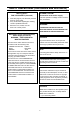
SAFETY PRECAUTIONS Place of storage and use Maintaining the unit (Please turn off the power before performing maintenance work.) Please avoid storing or using this DVR in the following places: Extremely hot or cold places beyond the Please wipe the unit with a soft cloth. Do not wipe allowable temperature for operation (5°C – it with thinner or benzene lest the surface melts or 40°C). becomes dull.
AC adapter section IMPORTANT SAFETY INSTRUCTIONS 1) Read all of these instructions. 2) Keep these instructions. 3) Heed all warnings. 4) Follow all instructions. 5) Do not use this apparatus near water. 6) Clean only with dry cloth. 7) Do not block any ventilation openings. Install in accordance with the manufacturer’s instructions. 8) Do not install near any heat sources such as radiators, heat registers, stoves, or other apparatus (including amplifiers) that produce heat.
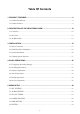
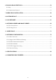
Table Of Contents 1. PRODUCT FEATURES ..................................................................................................... 9 1.1 Product Introduction .................................................................................................................... 9 1.2 Product Features.......................................................................................................................... 9 2. DESCRIPTION OF THE FRONT/REAR VIEW............................................
6. RS-232 & RS-485 PROTOCOL....................................................................................... 53 6.1 Setup........................................................................................................................................... 53 6.2 Communication Protocol:.......................................................................................................... 53 7. MOBILE RACK INSTALLATION..............................................................................
1. PRODUCT FEATURES 1.1 Product Introduction This DVR is a storage media of digital video image, which uses hard-disk drives instead of VCR tapes to store video. It enables you to enjoy the extreme flexibility of digital image archiving instead of clumsy tape management, and is compatible with most multiplexers in the market.
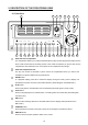
2. DESCRIPTION OF THE FRONT/REAR VIEW 2.1 Front View 1 Operate Display 23 Setup Search Enter Monitor 2 24 3 4 5 PLAY STOP PAUSE REC 6 REV FWD DISK OPERATE A-rec T-rec 7 8 9 10 11 14 13 12 15 16 17 18 19 20 21 22 Hard-disk drive compartment. The compartment allows you to install a hard-disk drive mostly for backup purposes. Make sure the drive is well secured with the mounting screws in the mobile rack before you put the rack into the compartment.
Setup button: Press this to enter the setup menu. Press again to exit the setup mode. Search button: Press to enter the search mode to access recorded video. Left / Right buttons: Press the two buttons to highlight desired items in the menu setup mode. For Key Lock operation, press these two buttons simultaneously once; to disable Key Lock, press these two buttons simultaneously again. Up / Down buttons: Press these two buttons to select the desired contents for programming in the setup menu mode.
Mobile Rack Power LED: Indicates the power status of the Mobile Rack. The green light indicates the Mobile Rack is activating. Mobile Rack HDD LED: Indicates the HDD status of the Mobile Rack. The orange light indicates the HDD is storing or retrieving data.
2.2 Rear View 25 26 27 28 29 30 31 SD Card FROM MUX MAIN MONITOR VIDEO AUDIO RS-485 IN IN 32 RS-232 OUT OUT TO MUX'S VCR IN ETHERNET 10/100 TO MONITOR ALARM 33 34 I/O 35 DC12V 37 38 36 VIDEO IN Connector: This BNC connector is used to connect the video output from a camera or a MUX to the DVR. FROM MUX MAIN MONITOR Connector: This BNC connector is used to connect the live video output from a MUX to the DVR.
2.3 ALARM In/Out DISK FULL ALARM RESET ALARM OUT RECORD IN GROUND 5 4 9 3 8 2 7 1 6 ALARM IN SWITCH OUT NO CONNECTION NO CONNECTION *THIS FIGURE IS LOOKED FROM THE REAR 1. GND: Ground Contact. 2. ALARM OUT (OUTPUT): This is an alarm output trigger. Connect this to external devices such as buzzers or lights. ( 3. 5V 0V(Active) ) 5V 0V(Active) ) RECORD IN (INPUT): This pin connects to a record trigger device for starting a record. ( 6.
3. INSTALLATION Please follow the instructions and the diagram below to set up the system. 3.1 Basic Connection CONNECTIONG TO THE AC ADAPTER Connect the provided AC adapter to the main unit. Screw SD Card VIDEO Clamp FROM MUX MAIN MONITOR AUDIO IN RS-485 IN ETHERNET 10/100 RS-232 OUT OUT TO MUX'S VCR IN TO MONITOR ALARM I/O DC12V DC IN terminal AC DC cord Provided AC mains cable Provided AC adapter (model:STD-1205) 1.
CONNECTING WITH A SINGLE CAMERA Please set the MULTIPLEXER option to OFF on the REC SETTING page in the setup menu when it is connected with a single camera. (Please refer to section 5.
CONNECTING WITH A QUAD Please set the MULTIPLEXER option to OFF on the REC SETTING page in the setup menu when it is connected with a quad. (Please refer to section 5.
ATTACHING AN EXTERNAL DEVICE TO DVR Connect an alarm out, alarm input, and a peripheral device as shown in the diagram below. Lamp SD Card VIDEO FROM MUX MAIN MONITOR AUDIO IN RS-485 IN ETHERNET 10/100 RS-232 OUT OUT TO MUX'S VCR IN TO MONITOR ALARM I/O DC12V Alarm Reset (Normally Open) 5 Ground 4 9 3 8 2 7 1 6 Alarm in (Normally Open) CLOCK SET Please set the clock before operating the DVR. (For operation details, please refer to section 5.
3.2 Hard-Disk Drive Installation The DVR is equipped with two compartments of hard-disk drive. The unit usually comes with one hard-disk drive installed in the compartment HD1, which is default-configured as a master. If you need a second hard-disk drive to be installed in the compartment HD2 (Mobile), please contact your distributors or installers for specific instructions on how to install it. Please don’t serve yourself before consulting your installers.
3.3 System Information You can display system settings information as shown on Table 3.3 A below at any time by pressing . In the playback mode, the recorded video information is displayed. In the live or the Display button recording mode, the Manual Recording information is displayed. However, when the DVR is displaying a decoded image from a multiplexer, you must first switch the unit to encoded image displaying (The pictures is switching swiftly and the light of Monitor button .
3.4 Updating System Software If the system software of the DVR needs to be upgraded, please contact your JVC dealer.
4. BASIC OPERATIONS This section shows you how to operate and manage the DVR when it gets in the way. 4.1 Configuring Recording Settings Recording Time settings (Recording Rate and Picture Quality Setting) Recording time will vary depending on the image size, recording rate, and the capacity of the hard-disk drives. Generally, the DVR comes with a built-in hard-disk drive for continuous recording from one to four weeks under most recording conditions.
NTSC (MUX ON) Audio OFF BEST Image HIGH Quality STANDARD BASIC Refresh Rate (Field/Sec) REC Time Mode 15.0 18.0 22.5 30.1 18.0 22.5 30.1 45.1 BEST HIGH STANDARD BASIC Refresh Rate (Field/Sec) REC Time Mode 30 20 12 5.5 2.4 1.22 0.71 1/4 1/6 1/8 4 hr 6 hr 12 hr 24 hr 48 hr 96 hr 168 hr 480 hr 720 hr 960 hr Possible Recording Time HDD=80GB ( hour ) 53.1 104.2 216.2 387.2 603.9 66.1 129.0 264.9 467.3 715.1 87.4 169.4 342.1 589.3 876.4 129.0 246.4 482.7 797.3 1131.
PAL (MUX OFF) Audio ON BEST HIGH STANDARD BASIC Refresh Rate (Field/Sec) REC Time Mode Possible Recording Time HDD=80GB ( hour ) 53.1 87.4 153.4 275.9 439.1 66.7 109.5 190.9 339.4 532.0 89.8 146.5 252.8 441.0 674.8 130.3 210.5 356.8 603.4 889.5 Image Quality 50 25 **17 **10 **5.5 2.9 1.52 0.88 1/4 1/6 1/8 3 hr 6 hr 9 hr 12 hr 24 hr 48 hr 96 hr 168 hr 480 hr 720 hr 960 hr 18.0 22.8 30.9 45.6 Possible Recording Time HDD=80GB ( hour ) 36.1 54.2 90.3 162.6 307.2 524.1 1825.3 45.6 68.
4.2 Recording Operations This section details the way to record video into hard-disk drives. Before commencing with the recording function, please configure the recording setting properly according to your needs. 4.2.1 Manual Recording When the DVR is in live display mode, take the following steps to start recording: to record video into a hard-disk drive with the (1) In live display, press the REC button corresponding programmed recording settings.
NOTE: You can proceed to start the scheduled recording from the current time if it is in the scheduled interlude as soon as setting is completed, and come out from menu to start recording. NOTE: If you activate the recording function before the scheduled recording, the unit will operate recording as shown in the diagram below and keep those Images in different files. 03:00 Start Manual Recording START END START 06:00 08:00 12:00 Timer Manual Timer NOTE: LIVE images may be freezed.
MAIN MENU MAIN MENU RECORD ALARM CLOCK / TIMER COMMUNICATION DISK SYSTEM RECORD ALARM CLOCK / TIMER COMMUNICATION DISK SYSTEM GOTO CLOCK / TIMER PAGE GOTO CLOCK / TIMER PAGE CLOCK / TIMER CLOCK REC ENABLE TIMER CLOCK / TIMER : SET : OFF : SET CLOCK REC ENABLE TIMER MAIN PAGE MAIN PAGE SET REC SCHEDULE TIMER REC ENABLE REC SCHEDULE START END S : 00:00-00:00 M: 00:00-00:00 T : 00:00-00:00 W: 00:00-00:00 T : 00:00-00:00 F : 00:00-00:00 S : 00:00-00:00 START END 00:00-00:00 00:00-00:00 00:00-00
4.2.3 Alarm Recording Take the following steps to activate the programmed alarm recording. For ALM OPERATION, REC RATE, REC QUALITY, AUDIO, ALM TYPE, ALM DURATION, and PRE-ALARM settings, please refer to section 5.2 for more details. (1) Press the Setup button to enter the MAIN MENU. (2) Select ALARM and press the Enter button to enter the ALARM SETTING. (3) Set the desired REC RATE, REC QUALITY, ALM TYPE, and ALM DURATION for use. If audio is required, set AUDIO to ON.
NOTE: The status of recording operations when an alarm takes place are shown in the diagrams below.
4.3 Playback Operations This section shows you how to operate the fast, slow, and single-picture playback functions, and details how the unit is to playback a file in a different operation status. Please refer to the following paragraphs specifying the relevant details. When playing a file, the monitor should display a flashing PLAY message and the PLAY button will light up indicating that the DVR is in the playback status. Operation Status A.
NOTE: When Normal playing a recorded video from a multiplexer at 60 F/S~30F/S (50F/S~25F/S for PAL), the playback speed is half at recorded speed NOTE: The playback speed will be displayed on the screen. However, when playing a recorded video from a multiplexer, the playback speed will only display in encoding (multiplexing) the mode. Press the Monitor button to switch between decoding and encoding modes. 4.3.2 Slow Forward/Reverse There are 4 speeds available for a slow playback: 1/2, 1/4, 1/8, 1/16.
4.3.4 Play Back Recorded Video from a HDD of the mobile rack To play back a recorded video from a HD2, take the following steps: (1) Press the Setup button to enter the setup menu. (2) Select DISK and press the Enter button to enter the DISK SETTING page. (3) Set the HD2 USAGE to REC and then exit the setup menu. (4) Use the search function to access desired recorded video. For specific operation details please refer to the next section 4.4 (Search Operations). 4.
4.4.2 Alarm list Search Take the following steps to proceed with the alarm-list search function. (1) Press the Search button to enter the search mode. (2) Select the ALARM LIST and press the Enter button to access the complete list of alarm-event recorded video. (3) Highlight the specific recorded video of your requirement and press the Enter button to display the selected video. (Key Operation: Press the and “^” and “v” buttons, to select a video; press the “<” “>” buttons, to flip over a page.
4.4.4 THUMBNAIL Search Take the following steps to proceed with the thumbnail search function. (1) Press the Search button to enter the search mode. (2) Select the THUMBNAIL and press the Enter button to access the thumbnail page. (3) Set the date you wish to search for the recorded video. (4) Press the Enter button to start searching and displaying the concerned image. ● You can set up by using the “<” button , the “^” button , the “>” button and the to move eye focus.
4.4.5 SD CARD Search Take the following steps to proceed with the SD card search function. (1) Insert a SD Card into the SD card slot of the rear unit. (2) Press the Search button to enter the search mode. (3) Select the SD CARD and press the Enter button to access the complete list of JPG files. (4) Highlight the specific JPG file of your requirement and press the Enter button to display the image.
4.5 Backup Operations 4.5.1 Mobile Rack HD Backup There are three ways available to duplicate the recorded video from HD 1 (Fixed HD) to HD 2 (Mobile Rack HD). Please take the following steps to proceed. (1) Set HD 2 to BACKUP first. Take the following steps. Press the Setup button to enter the setup mode and select the DISK. Highlight DISK and press the Enter button to enter the DISK SETTING page. Then set HD 2 USAGE to BACKUP.
MAIN MENU DISK SETTING RECORD ALARM CLOCK / TIMER COMMUNICATION DISK SYSTEM REFORMAT HD2 USAGE BACKUP----------------FULL ALARM SELECT MAIN PAGE BACKUP ALARM TO HD2 GOTO DISK PAGE SELECT: Duplicate a particular recorded video from HD1 to HD2. Stay on the DISK SETTING page. Use the “^” and “v” buttons, then press the Enter button Press the “^” and “v” buttons, and , to highlight BACKUP, select SELECT and to list all the recorded video. and , to select the desired clip and press the to mark it.
4.5.2 Security Digital Card (SD Card) Backup The SD card slot of the rear unit has three functions as shown below: 1. Archive Single image Clips into SD Card Please take the following steps to archive a critical image in a SD card. (1) Insert a SD Card into the SD card slot of the rear unit. (2) Start playing back the recorded video.
Transfer the system setting info of DVR to another: Insert the SD card which has stored the system setting info into the DVR. to enter the setup mode and select the SYSTEM. Press the Setup button Highlight SYSTEM and press the Enter button to enter the SYSTEM SETTING page. Then set SD SETUP to LOAD.
5. MENU SETUP There are 6 categories for operation setting in the setup menu system as shown below. The following sections will instruct you step by step to configure the operation setting and state each menu’s purpose and to access the setup menu. Once inside the menu system, the on-screen options. Press the Setup button menu allows you to set up the key features of the unit. The functions of various buttons within the menu-setup mode are described in the paragraphs below.
5.1 REC SETTING This page allows you to set the recording rate and recording quality, and enables you to continue recording when the disk is full. MAIN MENU REC SETTING REC RATE REC QUALITY DISK FULL AUDIO MULTIPLEXER RECORD ALARM CLOCK / TIMER COMMUNICATION DISK SYSTEM : 20 F/S : BEST : REWRITE : OFF : ON MAIN PAGE SET REC RATE GOTO REC PAGE REC RATE: This option is for adjusting the number of pictures recorded every second into a storage disk.
AUDIO: This option determines the way to record sound if necessary. ON: Enables AUDIO recording. OFF: Disables AUDIO recording. NOTE: Audio function can only be activated in the following refresh rate in NTSC(PAL): 12(10), 5.5(5.5), 2.4(2.9), 1.22(1.52), 0.71(0.88) fields/sec MULTIPLEXER: For optimum image recording please set this option to ON when the DVR is connected to a multiplexer for use. Set this option to OFF when it is only connected to a single camera or Quad processor. 5.
REC QUALITY: This option determines the image quality to be recorded when an alarm input occurs. There are 4 levels of image quality to choose from: BEST, HIGH, STANDARD, and BASIC. The table below shows the level of image quality with the corresponding compression ratio and image size. Image Quality Image Size Best Compression Ratio High Standard Basic 48KB 32KB 16KB 21KB AUDIO: This option determines the way to record sound if necessary. ON: Enables AUDIO recording. OFF: Disables AUDIO recording.
PRE- ALARM: This option determines that images prior to an alarm occurs will be recorded in the hard-disk drive. When an alarm is triggered the device will record the image prior to the alarm for 5 seconds in NTSC (**20 fields/sec) or 6 seconds in PAL (**17 fields/sec). ON: Enables this function. OFF: Disables this function. NOTE: If the device is already under recording mode before alarm occur, the pre-alarm recording would not take effect.
5.3 CLOCK / TIMER The DVR provides a weekly table, consisting of two periods of time each day for scheduled recording. This option allows you to set the time each day that the DVR will start and stop recording. MAIN MENU CLOCK / TIMER RECORD ALARM CLOCK / TIMER COMMUNICATION DISK SYSTEM CLOCK REC ENABLE TIMER : SET : OFF : SET MAIN PAGE GOTO TIMER PAGE TIMER REC ENABLE CLOCK: This entry allows users to set the system time.
5.4 COMMUNICATION This option allows you to configure the status of the RS-232 communication port when connected to an external device, and the Ethernet communications settings.
NET DHCP: This option selects enable or disable for the DHCP communication function. OFF: Disables it. ON: Enables it. NOTE: If provided with a DHCP server, the VR-601 can get an IP automatically by setting this option to ON. NET IP: This option is used to configure the Ethernet communication settings. This is required for the purpose of making a network connection. Please consult with a qualified MIS professional to configure it. IP: XXX.XXX.XXX.XXX MASK: XXX.XXX.XXX.XXX GATEWAY: XXX.XXX.XXX.
REC RATE: This option determines the recording rate to be recorded at when the FTP function occurs. There are 4 levels of recording rates to choose from: 1 F / 1 S, 1 F / 10 S, 1 F / 30 S and 1 F / 60 S. NOTE: An actual transfer interval could be stretched in some environment. ACCOUNT: This option is used to configure the FTP account settings. This is required for the purpose of making a FTP connection. Please consult with a qualified MIS professional to configure it.
5.5 DISK SETTING MAIN MENU DISK SETTING RECORD ALARM CLOCK / TIMER COMMUNICATION DISK SYSTEM REFORMAT HD 2 USAGE BACKUP GOTO DISK PAGE DISK REFORMAT/CLEAR : HD 1 2 : REC : FULL MAIN PAGE REFORMAT: This option allows you to clear out all the data in the hard-disk drive. You will be required to enter the pre-set password before proceeding with clearing out the data. Enter the standard password “9999” if you don’t set your individual password. To set your individual password, please refer to section 5.
5.6 SYSTEM This page is used for accessing the history of the operation status, setting the password, resuming factory default, and determining the menu display background.
MENU BACKGND: There are 3 levels of background color transparency, you can choose from : level 1 is totally transparent, level 3 is opaque, and level 2 is between level 1 and 3. The background color is used in setup menu and search function. BUZZER: This option determines the embedded buzzer sounding a tone to signal the following situations. A tone lasts about two seconds long. ON: Enables buzzer. OFF: Disables buzzer.
SD SETUP: The VR-601 offers a quick setup method by using a SD card. If the user wants to set up many a number of the same devices with the same settings, he can save the whole settings to a SD card, then transfer to another DVR. SAVE: Saves the whole setting to the SD card. LOAD: Loads the whole setting from the SD card. VERSION: This item is in the setup menu reveal network MAC, BIOS version, and software version, and last updated date. MAC : 00 : 0c : 0c : 00 : 00 : 07 BIOS : 1.05 SW : 1.
6. RS-232 & RS-485 Protocol 6.1 Setup 6.1.1 Use a Null Modem cable (the standard RS-232 9 Pin Cable with Pin 2 and Pin 3 exchanged, see pin configuration chart below for details) to connect the COM 1 on the rear panel of the DVR to a PC. 6.1.2 Set the RS-232 option to ON in the COMMUNICATION page of the setup menu. 6.1.3 Set the PC communication parameters: 9600 bps, No Parity, 8 Data Bits, 1 Stop Bit. 6.2 Communication Protocol: 6.2.
The different command types and their corresponding parameters are as follows: 6.2.
6.2.2 COMMAND Types 6.2.2.0 Command (Main Category=0x02) 6.2.2.1 Handshake (Second Category=0x01) PC Request: <0x41>, <0x01>, <0x20>, <0x02>, <0x01>, <0x00>, <0x4f> DVR Response: <0x41>, <0x20>, <0x01>, <0x02>, <0x08>, <0x00>, <0x4f> 6.2.2.
7. Mobile Rack Installation Usually, the unit comes with one hard-disk drive installed in compartment HD 1, which is default-configured as a master. The jumper settings configuration of the installed hard-disk drives for the unit and compatible drives which can be used with this unit are listed in the table below. To install a hard-disk drive in compartment HD 2, please take the following steps.
5. Attach the interface connector and the power connector to the drive. Please note the red lining of the IDE cable and the red wire of power cable must line up side by side. 6. Place the hard-disk drive inside mobile rack, Use four of the provided screws. 7. Place the top cover back to the carrier body by sliding forward to secure. 8. Slide the carrier body back in the mobile rack. 9. Push the carrier body further into the mobile rack until fully inserted.
10. Push the active-handle inward. 11. Lock the Key.
8.
MAIN MENU COMM SETTING RECORD ALARM CLOCK / TIMER COMMUNICATION DISK SYSTEM COMM ID RS232 RS485 NET ENABLE NET DHCP NET IP FTP SETTING : 01 : ON : ON : OFF : OFF : SET MAIN PAGE GOTO COMM PAGE SET RS232 / RS485 ID MAIN MENU DISK SETTING RECORD ALARM CLOCK / TIMER COMMUNICATION DISK SYSTEM REFORMAT HD 2 USAGE BACKUP : HD 1 2 : REC : FULL MAIN PAGE DISK REFORMAT/CLEAR GOTO DISK PAGE SYSTEM MAIN MENU OPERATION LOG MENU BACKGND BUZZER PASSWORD SETUP PWD DEFAULT SD SETUP VERSION RECORD ALARM CLO
9. O.S.D Message No. O.S.
10. Network Viewer and Image Viewer This section provides instructions for installing and using the Network Viewer, and Image Viewer, which are included with the VR-601. The programs can be operated by a selected PC equipped with the following requirements. 1. Intel Pentium 233MHz at least. 2. 32 MB RAM 3. Window 95, 98, NT, ME, 2000 and XP. 4. 4 MB Video card capable of 24-bit true color display. 5. 5 MB free hard-disk space for software installation. 6. 10-base T network for LAN operation. 10.
Physical specification for Ethernet Wire Type Connector Type Max. Cable Length Hub Wiring Configuration PC Wiring Configuration Cat. 5 RJ-45 30 m Straight Through Cross Over NOTE: For more details on network connections, please refer to the following document. 10.1.2 Install the Network Viewer in your PC Install the Network Viewer from the supported CD-R. 1. Exit all applications currently running in the selected PC. 2. Insert the supported CD-R in the CD-ROM drive.
10.1.3 View the VR-601 video from a remote PC Follow the instructions below to use the Network Viewer to browse a VR-601 video from a remote location. Upon entering the Network Viewer; the connection box will appear as follows. 1. Choose a channel number from the Channel drop-down list. 2. Assign a name for the chosen VR-601. 3. Type in the password and IP of the device and click the Add tag to add the device to the connection list. 4.
Viewing images View all the connected devices Once the connection has been established, click OK to enter the Multi-device mode window. (See the sample screen below) This window displays all the connected devices in the sequence which has been arranged when you established the connection. Function Buttons Description Split-Screen display function bar. This allows you to display the connected device in multi-format screens of 1, 2x2, 3x3, and 4x4.
View single device Follow any one of the instructions below to get into the single device mode. 1. Select the desired device from the DEVICE LIST box on the Multi-device Mode. The button will enable. Click the button to view the image of the selected device and have access to certain functional operations of the device via the network. (See the sample screen below.) 2. Double click the image display area of each screen.
Function Buttons Description Playback function bar. Play- Click to play back a recorded video from the PLAY LIST. Pause- Click to freeze the image. Stop- Click to stop playing back the recorded video or cease recording. REC- Click to activate the recording function of the device. Step- Click to view images picture-by-picture. Click to return to the Multi-Device mode. Click to save a viewing image in the local computer.
10.1.4 Change the Record & Timer Properties Via the Network Follow the instructions below to reconfigure the record and schedule recording settings via the network. A. Set the regular record settings 1. When in the single –device mode, click to enter the SETUP page. (See the sample screen as in A above) 2. Select a desired recording RATE and QUALITY from the corresponding drop-down list 3. Click the OK tag to proceed. Set the Alarm record settings 1.
10.1.5 Archive Images to the Computer Playback images can be stored in a local PC in the JPEG format. Follow the instructions below to save the viewed images to your PC. 1. Press during playback to freeze the desired image. 2. Press to enter the following sample screen. 3. Select a folder in the computer for copying images in. 4. Enter the number of images into the NUMBER OF SAVING box you wish to save in. 5.
10.2 The Image Viewer This is image integrity-protect software. It not only allows you to view an archived image from the SD card or HDD of a computer, but also protects an archived image from reproduction or interpolation. If an image isn’t in the original format made by a VR-601, the Image Viewer won’t display the image and instead will send a warning message” Wrong File, Can’t Open”. Follow the instructions below to open an archived image from a SD card or a HDD. 1.
11. Index Table The following description details how the DVR manages an index table issue. The DVR will generate a time index table indicating recorded data is kept in a particular HDD. This allows to individually selecting recorded data to be displayed via the alarm list search and full list search. The maximum number of lists, for a given HDD, is 3000. When the list of any given HDD is used up-and the disk is not full, The unit will still use the rest of the space for recording.
12. Network Configuration 12.1 Cable Connections Please follow the instructions below to connect your DVR to a computer or a network and to choose a proper RJ-45 cable configuration for connections. Physical specification of RJ-45 cable for Ethernet Wire Type Cat. 5 Connector Type RJ-45 Max. Cable Length 30 m Hub Wiring Configuration Straight Through PC Wiring Configuration Cross Over 12.1.1 Connect to a computer Use a crossover LAN cable to connect directly to a computer.
RJ-45 PIN configuration for LAN Hub PIN NO. 1. 2. 3. 4. 5. 6. 7. 8. PIN Assignment TX + TX RX + Not Connected Not Connected RX Not Connected Not Connected RJ-45 socket 12345678 12.1.3 Connect to WAN (INTERNET) The RJ-45 PIN configuration for connecting to a WAN is the same as connecting to a LAN. SD Card VIDEO FROM MUX MAIN MONITOR AUDIO IN IN ETHERNET 10/100 RS-232 OUT OUT TO MUX'S VCR IN RS-485 TO MONITOR ALARM I/O DC12V RJ-45 12.
12.2.2 Enable DHCP Function Use the “^” and “v” buttons , and , to highlight NET DHCP; select ON. Then to proceed. press the Enter button MAIN MENU COMM SETTING RECORD ALARM CLOCK / TIMER COMMUNICATION DISK SYSTEM COMM ID RS232 RS485 NET ENABLE NET DHCP NET IP FTP SETTING GOTO COMM PAGE SET ETHERNET DHCP : 01 : ON : ON : ON : ON : SET MAIN PAGE NOTE: This function can only work if the LAN which the unit is connected to has a DHCP server.
NOTE: When only one unit of the DVR is connected to a computer or LAN, you can freely assign an IP address for the DVR. For example, there is a range of DVR IP addresses from 192.168.0.1 to 192.168.0.255. You can pick one for use from the range of the IP. It’s not necessary to set MASK and GATEWAY; leave the settings as default. When a DVR is connected to a WAN, you must acquire a unique, permanent IP address and correctly configure the MASK and GATEWAY settings according to your network architecture.
Click the NETWORK icon twice to enter the NETWORK setting windows. Click on the Configuration tag; check if the TCP/IC is included among the network components list. If the TCP/IP is included, please process step 5. If it is not included, please follow step 4 to install the TCP/IP.
12.4 TCP/IP installation During the installation, you will be requested to insert the windows CD-ROM. After installation, the PC will be restarted. 12.5 TCP/IP Configuration setting Click Start Settings Control Panel Network. Select TCP/IP, and then click Properties. Before processing the DVR installation in a WAN, please make sure the Internet connection works properly. If not, please contact your ISP provider.
If you are using a DHCP server, please select Obtain an IP address automatically. Any assigned IP address for the connected DVRs must be in the same class type as the server. If there is no DHCP server, please select specify an IP address and type in the IP address of your PC. This IP address must be different from the DVR IP but in the same class type. NOTE: The IP address of a DVR in a network must be unique to itself as opposed to those of the other chosen PCs, but in the same class type 12.
If you receive a response as in the sample screen below, the connection hasn’t been successfully established. Please re-check all the hardware and software installation by repeating steps 1 to 5. If you still can’t establish the connection after rechecking, please contact your dealer. If you receive a response as in the sample screen below, you have successfully made the connection.
13.
14.