NETWORK VIDEO RECORDER VR-N900U INSTRUCTIONS Powered by Milestone Please read the following before getting started: Thank you for purchasing this JVC product. Before operating this unit, please read the instructions carefully to ensure the best possible performance. When this device is used as a general household, there is a possibility of radio disturbance to the radio and television receiver etc. For Customer Use: Enter below the Serial No. which is located on the body.
Introduction Hard Disk Drive Consumable Item The distance between the head and disk that read and write data on the hard disk drive (hereinafter known as the HDD) is a miniscule 0.02µm. Vibrations and physical shocks to the HDD may therefore result in the head coming into contact with the disk, producing dents and scratches to its surface. This will consequently prevent data from being read, and will result in disk crashes if use is continued.
Contents Playing Back Recorded Images..........................................16 Selecting a View..............................................................17 Searching for a Recorded Image ....................................17 Playing Back, Skipping and Stopping Recorded Images ..............................................................................18 Introduction Introduction...........................................................................
Introduction Defining a Preset Position............................................... 44 PTZ preset positions on events....................................... 45 Auto PTZ Patrolling ......................................................... 45 Camera Input/Output Port and Events ............................... 47 I/O Setup ........................................................................ 47 Configuring Event Buttons .............................................. 50 Specifying Generic Events .........
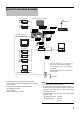
System Connection Example Preparation Analog cameras Speaker (with built-in amplifier) Microphone VIDEO IN 1–4 VIDEO IN 1–4 AUDIO OUT AUDIO OUT Alarm IN/OUT AUDIO IN ALARM IN/OUT Mic Amp REAR I/O Terminals Supplied power cable AC 120-240V 50Hz/60Hz VGA OUT LAN2 SERIAL VGA monitor Mouse LAN1 IP cameras Switching HUB Switching HUB Surveillance computer SERIAL UPS control * You can connect up to 9 cameras (of which up to 4 can be analog cameras).
Preparation CAUTION • Connect the IP camera after having turned off the system and connected devices. • Set the IP address of camera to 192.168.0.xxx. When setting the IP address of camera other than 192.168.0.xxx, you must also change the IP address of LAN1. As for the modification method of the camera’s IP address, refer to the instruction manual of each camera. • Do not connect LAN1 to the internet. If the internet is busy or the relay equipment fails, you may not be able to save important camera images.
Clock Display Changing monitor resolution The VR-N900U has a clock display function that displays the current time on the screen. Press the [ZOOM OUT/CANCEL] or the [ZOOM IN/ENTER] button while holding down the [FUNCTION] button to change VGA output resolution. 1 Press the [2/ ] button while holding down the [FUNCTION] button. CAUTION Clock display appears on the screen. • Selecting a resolution not supported by the monitor may prevent normal monitor synchronization.
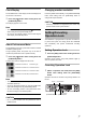
Basic Operation Switching the Power On/Off Switching Operation On/Off by Pressing the Button on the Front Panel Basic Operation You are able to switch operation on or off. Switching the Power On 1 Connect the power cable. Connect using the power cable supplied to an AC 120V 240V 50Hz/60Hz outlet. 2 Turn on the power switch on the rear panel. • A system check will run when the power is turned on. • The [OPERATE] indicator will blink.
Switching Operation On/Off by the Rear Input/Output Terminals Login • For details on the rear input and output terminal layout, refer to “Rear I/O Terminals” (Page 9) in the STARTUP GUIDE. If [Auto Login] is set to [Off], the [Login] window will appear after the system activates. Use the keypad to enter your password and press the [ZOOM IN/ENTER] button. Switching Operation On Note 1 (With operation off status) Press the [OPE ON/ OFF] button.
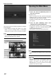
Basic Operation Opening the Main Menu 1 Press and hold the [REC/STOP] button for more than 2 seconds. Recording will stop. • When in recording control mode, press and hold the [REC CONTROL] button for more than 2 seconds to switch the recording control mode off and stop recording. • For details of recording mode, refer to “Recording Modes”. ( ☞ Page 24) Wallpaper screen When login has been successfully completed, the wallpaper screen will appear.
Main Menu Contents Using the VR-N900 Viewer The Main Menu contains the following menus. Select the required item with the [2/ ] or [8/ ] button and specify the settings. Press the [ZOOM IN/ENTER] button to save the settings and press the [ZOOM OUT/CANCEL] button to close the menu and return to the Main Menu. You can view live and recorded images with the VR-N900 Viewer. You can also use the VR-N900 Viewer when monitoring the VR-N900U from a surveillance computer.
Basic Operation Viewing Live Images Selecting a View For details of creating views, refer to “Screen Setup”. ( ☞ Page 30) 1 Display the [Live Viewing] window 1 Press the [LIVE/BROWSE] button or select [Live Viewing] in the Main Menu. • The VR-N900 Viewer starts up and the [Live Viewing] window appears. • If the setup window is displayed, close the setup window. • If the [Browse] window is displayed, press the [LIVE/ BROWSE] button.
• You can change the camera number in the [Record Camera Setting] window. ( ☞ Page 38) If you press 0 first and then enter the camera number, you can specify numbers from 10 to 19. Use the mouse to specify numbers from 20 upwards. Note • When you select a particular camera, the blue bar at the top of each live image becomes a lighter blue. Each bar features three-color square indicators with the following functions.
Basic Operation • You are able to use the PTZ Navigation buttons in the [PTZ Control] section to move the selected PTZ camera. The round middle button lets you quickly move the camera to its home position. The [+] and [-] buttons lets you zoom in and out respectively. CAUTION • The buttons are only available if the camera is a PTZ camera.
●How to Manually Trigger an Event ●Camera Shortcut Menus To manually trigger an event, select the required event in the [Event] section, and click the [Activate] button. By right-clicking inside one of the images from the camera, you get access to a shortcut menu. Some of the shortcut menu’s content may vary from camera to camera, depending on the configuration of the selected camera. [Event] section [Live Viewing] window Note • For details of events, refer to “Camera Input/Output Port and Events”.
Basic Operation Playing Images Back Recorded [Views] section [Close] button CAUTION • The recording frame rate may decline when using the [Live Viewing] window. • For the area(s) that do not support the Daylight Saving Time (DST). If DST is entered, the sections where a change to DST is made may not be properly played back or searched.
Selecting a View The specified date and time will appear in the [Master Time] area. 1 Note Press the [PTZ/PRESET] button until the [PTZ/ PRESET] indicator blinks. 2 Press the [ZOOM IN/ENTER] or [ZOOM OUT/ CANCEL] button to select a view. Note If you connect a mouse, you are able to select a view in two ways: • By selecting the required view in the [Views] section. • By selecting the required view from the [Views] list located in the upper part of the window.
Basic Operation ●Using the [Timeline Browser] You can browse through recorded images using the [Timeline Browser] on the right of the [Browse] window. The vertically extended timeline shows the recording status and reflects only the number of cameras displayed in the VR-N900 Viewer. Drag on the timeline up or down with the mouse while checking the time display pointer. • The timeline is only a rough guide and may differ from actual time.
Stopping Time Slider 1 Moving the slider to the left changes the recording date to an older date and moving the slider to the right changes it to a more recent date. Use the top bar for fine browsing (x0.4 to x240) within a limited period of time and use the bottom bar for easy browsing (x20 to x36,000) for longer time spans. Press the [STOP(PB)] button. Playback will stop.
Basic Operation Adjusting the Playback Speed (Jog/ Shuttle Playback) Sequence [Sequence] bar You can adjust the playback speed by turning the jog dial/ shuttle dial on the front panel. Shuttle Playback • Rotate the shuttle dial during playback or when playback is paused to start fast forward, fast reverse or slow playback.
You are able to click the listed events to view recordings from the required event in the view. Note • The Alerts list displays events occurring in the time period (approx. 1 day before and after) set in [Time navigation]. Smart Search Smart Search lets you specify motion in one or more selected areas of images from a particular camera. ( ☞ Page 54) 1 Double-click the [Smart Search] bar in the [Browse] window.
Basic Operation 7 Click the [Next] or [Previous] button to search Select the required camera from the Source through data with motion detected in the list and click the [AVI/JPEG Export] button or selected areas. [Database Export] button. The Smart Search will begin. When motion is detected inside the selected area(s), it will be highlighted in the view. CAUTION • Smart Search is carried out forwards or backwards from the time of the image you are viewing.
8 If you selected database format, the following items can be specified. 11 If you selected database format, you are able to Include Audio: Select this check box to include audio in the export (if no audio sources are attached, the check box will not be available). Compress Exported Database: Select this check box to compress the exported database. Encrypt Exported Database: Select this check box to encrypt the exported database. Specify a password for subsequent decryption.
Basic Operation Printing the Recorded Images Recording Camera Images You may print the playback image that is displayed. CAUTION • This function is not available with the VR-N900U. • This function is for the downloaded VR-N900 Viewer. 1 Double click the [Print] bar in the [Browse] window. [Browse] window 2 Recording Modes ●Recording Control Mode In this mode, recording is carried out in accordance with the [Camera Record Setting]. The [REC CONTROL] indicator is lit.
Recording by EXT REC IN signal has priority over recording control mode or manual recording. When recording by EXT REC IN signal is finished, the cameras will return to the original recording mode. Note • The [REC CONTROL] indicator goes off and the [REC] indicator blinks during recording by EXT REC IN signal. • Recording will start or stop from all cameras, regardless of the [Scheduler] settings or [Camera Settings].
Basic Operation Selecting the Manual Recording Mode 1 1 Select [Camera Record Setting] from the Main Menu. [Scheduler] button Press the [REC/STOP] button. The unit enters the manual recording mode and starts recording from all cameras. The [REC] indicator lights up. • To stop manual recording, press and hold down the [REC/ STOP] button. The [REC] indicator goes off. • To clear all modes, press and hold down the [REC/STOP] button. [REC] indicator 2 Click the [Scheduler] button.
Note • To cancel the period, select [Clear] from [Mode] at the top left, select the check box you want to cancel ([Online], [E-mail] or [Patrolling]), then move the mouse pointer while left-clicking the mouse on the period in the calendar section. ●Buttons Copy Schedule: Lets you copy the schedule displayed in the calendar section. Paste Schedule: Lets you paste a copied schedule in the Copy Schedule for use with the selected camera.
Basic Operation Camera Administration 1 Select [Camera Record Setting] in the Main Menu. ● Image storage settings Desired framerate: Lets you specify the recording frame rate. You cannot select a higher value than the [Framerate] specified in the [Speedup Settings]. CAUTION Settings [Camera Record Administrator] window 2 Select the required camera in the [Device Manager] section and click the [Settings] button. The [Camera Settings for Device Name] window will appear.
[Number of] seconds pre/post recordings on motion/ event: You are able to store recordings from periods preceding and following detected motion and/or specified events. Specify the number of seconds for which you want to store images from before and after the recording. Please do not set it at 0 (zero) second. If Offline is selected in [Scheduler], images will not be recorded. Manual recording, emergency recording and recording with EXT REC input will not be effected.
Basic Operation Screen Setup Creating Groups and Views ●Creating Groups 1 About Groups and Views Select [Screen Setup] from the Main Menu. If the [Live Viewing] window or [Browse] window is displayed, you can also click the [Setup] tab with the mouse. Multi-view setting from multiple camera(s) is called “view”. All views are placed in folders called groups. ● Groups can be private or shared. ■ Private: Views in this folder can only be accessed by the user who created them.
4 Enter a group name of your choice. A new view is created under the group you selected. ●Creating a [View] in a [Group] 1 Select the group in which you want to create the view. Main Menu CAUTION • Do not display more than 10 windows at once. 3 2 Enter a view name of your choice. Click the [Create New View] button. Next, add cameras to the view. ( ☞ Page 32) ●Renaming [Groups] or [Views] 1 Select the group or view that you want to rename in the Views section.
Basic Operation 2 Click the [Rename] button. [Screen Setup] window [Server] 3 and drag the camera name on top of the view [Rename] button 3 Overwrite the existing group or view name with a new name of your choice. Select the camera you want to add from the list screen in the view on the right. • An image from the selected camera will appear, together with the camera name. • Repeat the procedure for each camera that you want to add.
Maintain Image Aspect Ratio: If this check box is selected, the cameras’ original image aspect ratio will be maintained. CAUTION • The recording frame rate may decrease when the image quality is set to [High] or [SuperHigh (for megapixel)]. Adding Carousels A carousel is used for displaying images from several cameras, one after the other, in a single view position. Also, you can set the changeover intervals of the required camera. 1 Display the [Screen Setup] window.
Basic Operation 3 Drop the [Carousel] icon over the required position. Note • The green border indicates that the position is used for a carrousel. • The sequence in which cameras will appear in the carrousel is automatically determined by their names. The cameras will appear in alphabetical order, then loop continuously. Adding Matrix Content Settings for using Milestone XProtect Matrix made by Milestone Systems. For detailed information, please refer to the Smart Client 3.
Using HTML Pages Adjusting Camera Settings 1 1 Click [Html Page] in the [System Overview] section. [Screen Setup] window. 2 [Html Page] 2 Select the camera you want to adjust in the Select [Properties] with the mouse. [Screen Setup] window Drag and drop the [Html] icon to the required [Screen Setup] window position. The [Open URL] window will appear. 3 Adjust the following camera settings when necessary. [Open URL] window 3 Type the URL and click the [OK] button.
Basic Operation Always off: Does not sound alerts when events related to the camera occur. Always on: Play a sound alert each time an event related to the camera occurs. CAUTION • Set the VR-N900U so that the total frame rate that appears on all surveillance computers is 30 ips or less. • The recording frame rate may decrease when the image quality is set to [High] or [SuperHigh (for megapixel)]. • The alert sound at the time of motion detection and on event will not output from VR-N900U.
Customizing Joystick Setup 1 Click the [K] button on the right side of the window’s tool bar. [K] button 2 From the menu that appears, select [Joystick Setup]. 3 Select the required joystick in the [Selected Joystick] list. [Selected Joystick] list [Axis Setup] section Invert: By default, a PTZ camera will move to the right when you move the joystick to the right along the X-axis, move up when you move the joystick towards you along the Y-axis, etc.
Applications Camera Number: Lets you specify the camera number. Camera Record Setting Window Applications Display the [Camera Record Setting] window 1 Select the [Camera Record Setting] in the Main Menu. CAUTION The [Camera Record Setting] window will appear. • It is highly recommended that you use an alternative camera number for each camera. When the camera numbers have overlapped, the camera may not operate properly.
● Buttons Service Manager: The [Service Manager] button opens the small [Service Manager] window, which lets you pause/resume the recording program “Recording Server”. Pausing the service is necessary in order to access some features, for example configuration of PTZ cameras. ● Analog Cameras In the VR-N900U, analog input circuitry is considered a network encoder (IP video server) and the IP address 192.168.201.12 has been set. The registered address [N900 (192.168.201.
Applications Adding Cameras Camera are connected to devices, so first it is necessary to add the required devices such as network camera or network encoder (IP video server) to the system. Devices have their own IP addresses or host names and the system identifies the devices based on their IP addresses or host names.
● Adding an Analog Camera To add an analog camera manually, specify “192.168.201.12” as the IP address in the [Device Setup Wizard]. As no password has been specified, leave the password entry field blank and continue to the next step. Note • By default, analog cameras are already added. [Edit Device Settings] window The [Edit device settings] window lets you edit the settings of an already installed device.
Applications [Camera Settings for Device Name] window The [Camera Settings for Device Name] window lets you specify certain information about cameras. The number of settings available in the [Camera Settings for Device Name] window may be limited if cameras are not PTZ cameras or device connected to a network encoder (IP video server). To access the [Camera Settings for Device Name] window, click the [Camera Settings] button in the [Edit device settings] window.
Defining a PTZ Preset Position Display the [PTZ Preset Positions] window The [PTZ Preset Positions] window lets you define preset positions for the PTZ cameras. Pausing the Recording Server When defining PTZ camera settings, it is necessary to pause the recording server. 1 1 Select the [Camera Record Setting] in the Main Menu. 2 Select the required camera in the [Device Select the [Camera Record Setting] in the Main Manager] section and click the [Settings] Menu. button.
Applications 3 Click the [PTZ Preset Positions] button. The [PTZ Preset Positions for Device Name] window will appear. Set Position: Associates the preset position selected in the list with the position specified in the [PTZ View] section. Edit Name: Lets you edit a preset position name selected in the list. Test: Lets you test a defined preset position. Select the required preset position in the list, then click the [Test] button. The effect is displayed instantly in the [PTZ View] section.
and a particular event, select the required event in the window’s rightmost list, and click the [ ] button. 5 To define another preset position, repeat steps 2 to 4. PTZ preset positions on events This feature lets you make the PTZ camera automatically go to a particular preset position when a particular event occurs. 1 Display the [PTZ Preset Positions] window. Auto PTZ Patrolling PTZ patrolling is the automatic movement of a PTZ camera between several preset positions.
Applications Copy: Let you create a new patrol scheme based on an existing one. Select the required patrol scheme to copy in the [Patrol Scheme] list beforehand. Rename: Let you change the name of an existing patrol scheme. Select the required patrol scheme to rename in the [Patrol Scheme] list beforehand. Remove: Let you remove an existing patrol scheme. Select the required patrol scheme to remove in the [Patrol Scheme] list beforehand. 3 moves between two preset positions.
Camera Input/Output Port and Events The input/output port is the input/output terminal which is equipped in each device that is registered to VR-N900U. The input port as can be registered as “Input Event” and for the output port as “Output” can be registered. As for the registered input/output port, it is associated with the following explanation and which can be linked to this event.
Applications Input events for device: Read-only field, displaying the name of the device on which the input events are defined. Available Input Event(s): Lists available input events for the device. Enabled Input Event(s): Lists enabled input events for the device. : You enable an event by selecting it in the [Available Input Event(s)] list, then clicking the [ ] button. : Lets you move an input event selected in the [Enabled Input Event(s)] list to the [Available Input Event(s)] list, thus disabling it.
Specify a VMD event 1 Select the required camera to specify VMD 2 Click the [Add new event] button. The [New Timer] window will appear. event from the [Enabled Input Event(s)] list in the [I/O Setup] window. 2 Click the [Add new VMD event] button. If the selected device is a multi-camera device, such as a network encoder (IP video server), a simple dialog in which you select the required camera will appear.
Applications 3 Select the output connection destination and specify the amount of time for which the output should be maintained and the name of the output. External output connected to: Read-only field, displaying the name of the device on which the output event is defined. Output connected on: Lets you select the connections of the device’s output ports. Keep output for: Lets you specify the amount of time for which the output should be applied, in either 1/10 seconds or seconds.
2 Select Generic and click the [Add new event] button. [Add New Event] window Button related to: Read-only field, displaying the name of the camera for which the event will be specified. Manual event name: Lets you specify a name for the event button. Send e-mail if this event occurs: Select check box to send an e-mail alert when the event button is clicked.
Applications ● Event Rule String Event substring: Lets you specify the individual items for which VR-N900U should look out when analyzing data packages. Specify one or more terms, then click the [Add] button to add the specified term(s) to the [Event message include] field. When you add several terms as one item, everything between the quotation marks must appear together in the package, in the specified sequence, in order to match your criterion.
Specifying an Output Port A specific event or the clicking of an event button can be associated with a particular output port. To do this, specify the output port from which output will be triggered when a specific event or manual action occurs. 1 Select [I/O Control] in the [Camera Record Setting] window. ● Selecting Output for Manual Control You are able to specify outputs to be triggered manually through output button or from a list in the [Live Viewing] window.
Applications Motion Detection Settings You can configure the camera’s motion detection. You can specify when images from the camera are transferred, when alerts are generated and when external outputs (the switching on of the lights or the sounding of a siren) are triggered. CAUTION • Motion detection is a key element in system operation, and time spent on finding the best possible motion detection settings for each camera may help you later avoid unnecessary alerts.
2 Left click and drag the mouse pointer over the grid sections in the preview image to select Other Settings the areas in which motion detection will be disabled. Selected areas are highlighted in blue. To clear areas in which motion detection has been disabled, right click and drag the mouse pointer over the required grid sections. Buttons and Check Boxes Set All: Lets you quickly select all grid sections in the preview image. Clear All: Lets you quickly clear all grid sections in the preview image.
Applications Create default schedule for new cameras: If selected, a schedule specifying that the camera is always online will automatically be created in the [Camera/Alert Scheduler] window. ● [Email Settings] This lets you enable and configure the use of e-mail alerts. [E-Mail setup] window The following items can be specified. Enable E-Mail (Monitor): Select the check box to enable use of e-mail alerts. Recipient(s): Specify e-mail addresses to which alerts should be sent.
Max. records in database: Select this option to limit the database size based on a maximum allowed number of records in the database. Specify required maximum number of records in the neighboring field. If [Automatic archive when database is full] is turned off and when the maximum number of records in the database is reached, the oldest record in the database will be automatically overwritten. Max.
Applications 4 Select the required cameras for which the archiving function should apply. CAUTION • Recorded images may be lost in the recording performed while archiving. Unit Setting Unit Setting lets you specify account configuration, error recovery, serial port and other VR-N900U-related settings. Note • If audio is enabled while recording, audio data from the device will also be archived. ● Fields, checkboxes and buttons Enable Archiving: This function is not available.
[Mail Server] Lets you define the necessary information regarding the mail server if you selected [Mail] for the [Error Report]. ■ SMTP server is the server to be used for sending e-mails. ■ POP server is the server to be used for receiving e-mails. ■ Lets you select the method for authenticating users when sending e-mail through the mail server. You can choose from SMTP Authentication, POP before SMTP and NONE. Consult your system administrator if in doubt.
Applications CAUTION • Do not change the analog camera network settings unless absolutely necessary. If changes are unavoidable, consult your nearest JVC dealer. • When a host name is modified, it is necessary to “Add the Windows user” with the [User Administration] of the [Image Server Setting]. ( ☞ Page 64) • Do not set the default gateway in each of the camera network and intranet in the [OS Setting] window. The operation may not function properly.
4 Select [Remove Flash Memory]. 4 read the settings data. Click the [OK] button. • You will be asked to confirm that you want to remove the flash memory. Click the [OK] button. • A message informing you that the flash memory has been removed will be displayed. Click the [OK] button. 5 You will be asked to confirm that you want to Remove the flash memory from the SERIAL port on the front or rear panel. Note • Settings data is saved to the VR-N900 folder in the flash memory (USB memory).
Applications Auto Detect Setting You can assign an IP address to each camera and configure various settings concerning auto detect settings. [Gateway] Specify the gateway for the camera(s). [DNS Server] Specify the DNS server address for the camera(s). [Domain Name] Specify the domain name for the camera(s). [Lease Time Limit] Specify the validity period of the IP address assigned to the camera(s). If [Yes] is selected, you can set the lease time on an hourly basis.
1 CAUTION • Deselecting [Analog Input] disables the [ALARM IN 1 to 4] signal input terminals on the rear panel. • When operating the auto detect function and “Do not detect in the future.” is selected in the [Detecting Device] window, the [Detecting Device] window of the corresponding camera will not be displayed with subsequent auto detect operation, but even with the camera which is out of the detection can be added ( ☞ Page 40) manually. Select [HDD Utility] in the Main Menu.
Applications Language Setting Image Server Setting Let you specify the language you want to use. The function of the button and the GUI (graphical user interface) are the same as the [Language Selection] window that is displayed when the recorder is first switched on. When setting the language, shut down the VR-N900 Viewer. Lets you specify settings for connecting the VR-N900U to a computer and for displaying the [Live Viewing] window and [Browse] window. 1 Select [Language Setting] in the Main Menu.
CAUTION • You have to set up port forwarding and provide a path via routers and firewalls to allow a surveillance computer connected to the Internet to access the system. For details, refer to the manuals supplied with the equipment. Outside IP Address: Lets you specify a public IP address for use when the server should be available from the internet. Outside Port: Lets you specify a port number to use when the server is available from the internet.
Applications Full Access for All Users: Select this option to give all the users access to all VRN900 Viewer features and all available cameras. Restricted Access: Select this option to use restricted access. Then click the [User Access] button to define access rights for each user. How to Define Rights for Individual Users 1 Select [Restrict user access] in the [User Administration] section.
7 Specify the features for each camera now listed in the [Viewable by selected user] list. The following features, all selected by default, are available: Live: Ability to view live images from the selected camera. PTZ: Ability to use the VR-N900 Viewer’s navigation features for PTZ cameras. PTZ Preset Positions: Ability to use the VR-N900 Viewer’s navigation features for moving a PTZ camera to particular preset positions. Outputs: Ability to trigger outputs (e.g.
Applications Computer Network Settings The following example is for building a small-scale LAN using Windows XP professional and the VR-N900U settings at the time of shipment. (All screens shown below are Windows XP SP2 setup windows.) 1 Click the [Start] button and choose [Control Panel]. 3 Select the network to which the VR-N900U is connected. 2 Under “Pick a Category”, click [Network and Internet Connections] and then under “or pick a Control Panel icon”, click [Network Connections].
Installing the VR-N900 Viewer on Your Computer Make sure that Microsoft .NET Framework 2.0, DirectX 9.0 or later and Microsoft Internet Explorer 6.0 have been installed on the PC where you are going to install the VRN900 Viewer, as installation may otherwise fail. 1 Open an Internet Explorer browser (version 6.0 or later) and enter the IP address of the VRN900U (192.168.1.253). 7 Select [Use next IP address]. 8 Specify 192.168.1.11 for the IP address. 9 Specify 255.255.255.0 for the subnet mask.
Applications 3 Click the [Run] button. The VR-N900 Viewer Setup Wizard begins. 4 Click [Next] and follow the installation instructions. Installation ends and a shortcut to [VR-N900 Viewer] is created on the desktop.
Log In to the VR-N900 Viewer 1 Double-click the [VR-N900 Viewer] shortcut on your desktop. If the [VR-N900 Viewer] desktop shortcut is not shown, select the [VR-N900 Viewer] from Windows’ [Start] menu The [VR-N900 Viewer] log in window will appear. 2 Specify your login information in the following fields. Server address: Type the IP address and port number of the VR-N900U. (example: http://192.168.1.253:80, where :80 is the port number.
Applications CAUTION • When you log out in a state of maximum number of clients, it is necessary to wait several minutes next time you connect. • When multiple computers are connected and audio is played back, the audio may be distorted. • When you logout from a VR-N900U which is in the midst of connecting and reconnecting with another VR-N900U, reboot ( ☞ Page 11) the VR-N900 Viewer. Log Out and Exit the VR-N900 Viewer [Log out] button ● Logging out 1 4 Select your language as the interface language.
Compatible Equipment Connecting a UPS Connecting an uninterruptible power supply (UPS) to the hard disk will protect it from damage by automatically powering down all operations prior to switching off the power supply in the event of a power failure.
Others External Hard Disk Drives The system can have additional hard disk drive upgrade of one 500 GB external hard disk drive, one 1 TB external hard disk drive and two 2 TB external hard disk drives (you cannot combine different capacities of hard disk drives). Follow the procedure below to format the hard disk. 1 Press the [OPERATE] button for two or more seconds to set operation to off mode. 2 Switch off the power switch on the rear panel. Make sure the power switch turned off.
Recording Time Schedule The actual recording time varies depending on the camera settings, input image contents and condition of the hard disk. Use the tables below as a guide to the recording time.
Others • 4 channel recording without audio recording or additional HDD upgrade Image Size VGA QVGA Data/Image [kB] 30 32 24 16 10 27 15 8 5 15 14 19 29 47 17 31 60 96 28 38 59 95 34 63 119 192 [hour] 1 channel, 1 second per framerate/channel 10 5 3 1 430 42 85 141 58 115 192 581 176 293 884 88 284 474 1428 142 169 514 51 102 188 313 944 94 179 357 595 1791 287 575 958 2880 0.5 0.
Default (Initial) Value List Scheduler (Specifying a Scheduler, Page 24) Online Speedup E-mail Patrolling [ ]: Factory default [Always online] [Always offline] [Always offline] [Always offline] Camera Record Settings ([Edit Device] - [Camera Settings], Page 42) PTZ Camera Settings Pan/Tilt/Zoom(PTZ)Camera is connected Camera Type [Not selected] [Fixed] Camera Administration (Camera Recording Setting, Page 28) Speedup Settings Framerate Frame/ [8] [Sec.]/Min.
Others Other Settings (Other Camera Settings, Page 53) Milestone XProtect Central Settings Section Enable Milestone XProtect Central Connections [Not selected] Patrolling Settings Resume Patrol after Manual or Event PTZ (sec.
Mail Server Settings SMTP Server POP Server SMTP Authentication Emergency Recording Time of Record Encode Mode Interpolate Serial Settings Speed Data Length Parity Stop Bit Comment OS Setting (OS Setting, Page 59) Network adapter interface name Realtek RTL8169/8110 Family Gigabit Ethernet NIC: LAN1 (Camera network) Obtain an IP address automatically IP address Subnet mask Default gateway Preferred DNS server Alternative DNS server Host name DNS domain name Enc Board Driver: Analog camera network Obtain an
Others Intel® 8225xER PCI Adapter: LAN2 (Intranet) Obtain an IP address automatically IP address Subnet mask Default gateway Preferred DNS server Alternative DNS server Host name DNS domain name Date and Time Properties Automatically synchronize with an Internet server Time zone Auto Detect Setting (Auto Detect Setting, Page 62) IP Lease [Not selected] [192.168.1.253] [255.255.255.0] [192.168.1.254] [0.0.0.0] [0.0.0.
Troubleshooting Problem Power cannot be turned on. Solution Check that the power cable has been plugged in correctly. Check that the power switch on the rear panel is switched on. Camera is not automatically detected. Follow the instructions in the camera’s user manual and check the DHCP settings. Unable to operate the system by pressing the [REC] or [PLAY] button. Check that operation lock is not engaged. No images are recorded with recording control mode.
NETWORK VIDEO RECORDER VR-N900U ©2007 Victor Company of Japan, Limited LST0497-001A