is a registered trademark owned by VICTOR COMPANY OF JAPAN, LTD. is a registered trademark in Japan, the U.S.A., the U.K. and many other countries. © 2003 VICTOR COMPANY OF JAPAN, LIMITED VICTOR COMPANY OF JAPAN, LIMITED R Printed in Taiwan VR-601 DIGITAL VIDEO RECORDER Thank you for purchasing this JVC product. Before operating this unit, please read the instructions carefully to ensure the best possible performance.
19. 18. 17. 16. 13. 14. 15. 12. 11. 10. 9. 8. 7. 5. 6. 1. 2. 3. 4. 2 Read all of these instructions. Save these instructions for later use. All warnings on the product and in the operating instructions should be adhered to. Unplug this appliance system from the wall outlet before cleaning. Do not use liquid cleaners or aerosol cleaners. Use a damp cloth for cleaning. Do not use attachments not recommended by the appliance manufacturer as they may cause hazards.
RED colour indications on the operation panel are provided but they are not safety related. RED colour indications: (1) For Recording Button. CAUTION It should be noted that it may be unlawful to rerecord pre-recorded tapes, records, or discs without the consent of the owner of copyright in the sound or video recording, broadcast, or cable programme and in any literary, dramatic, musical or artistic work embodied therein. WARNING FOR CONTINENTAL EUROPE, ETC. Not to be used in the U.K. 4 FOR U.K.
instructions unless you are qualified to do so. 6 risk of electric shock, do not perform any servicing other than that contained in the operating CAUTION – These servicing instructions are for use by qualified service personnel only. To reduce the shall be placed on the apparatus. Apparatus shall not be exposed to dripping or splashing and no objects filled with liquids, such as vases, WARNING - To reduce the risk of fire or electric shock, do not expose this apparatus to rain or moisture.
8 14. COMPATIBLE MULTIPLEXERS ................................................................................... 80 13. SPECIFICATIONS ......................................................................................................... 79 12.6 Connection Testing................................................................................................................. 77 12.5 TCP/IP Configuration setting .........................................................................................
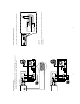
8 7 9 Setup 10 Search 11 14 13 12 15 Enter 16 Monitor 23 17 T-rec A-rec 2 18 24 19 DISK REV 3 REC PAUSE 21 STOP PLAY 20 5 4 22 OPERATE FWD 6 10 Press this to enter the setup menu. Press again to exit the setup mode. Setup button: Press to show the system operation status on the screen. DISPLAY button: Press this button for at least 3 seconds to power off. Press again to activate the device. OPERATE button: REC mode.
OUT 33 34 AUDIO OUT IN ETHERNET 10/100 28 RS-485 RS-232 I/O 35 ALARM SD Card 29 30 31 37 38 36 DC12V 0V(Active) 5V ) 0V(Active) 5V ) ) 0V(Active) 5V ) same recording speed as the DVR. multiplexer, connects to a multiplexer’s trigger terminal so the multiplexer can switch to use the Normally Open or Normally Closed.
TO MONITOR AUDIO OUT IN ETHERNET 10/100 RS-232 I/O DC12V DC IN terminal The orange light signals the hard-disk drive is power stand by. 14 * About the location of the buttons, please refer to Page 10 2.1 Front View. • Even in the OPERATE OFF mode, a small amount of electricity will still flow into the unit. • When the unit is in the OPERATE OFF mode, no operation can be performed except that of the OPERATE button.
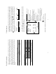
Trig In Monitor Quad Monitor TO VIDEO Audio in Video in FROM MUX OUT IN MONITOR TO FROM MUX MAIN MONITOR MONITOR TO MAIN MONITOR IN OUT MUX'S VCR IN Audio in S-video VIDEO TO MUX'S VCR IN Video in S-video Multiplexer ETHERNET 10/100 GROUND OUT IN OUT IN 16 AUDIO OUT IN Audio OUT IN ETHERNET 10/100 SWITCH OUT AUDIO Audio 9 RS-485 5 RS-485 4 I/O I/O 7 RS-232 3 ALARM SD Card 8 RS-232 ALARM SD Card 2 6 PC 1 PC DC12V DC12V when it is connected with
pictures is switching swiftly and the light of Monitor button consulting your installers.
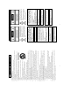
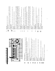
20 If the system software of the DVR needs to be upgraded, please contact your JVC dealer. 3.4 Updating System Software BEST Image HIGH Quality STANDARD BASIC Refresh Rate (Field/Sec) REC Time Mode 21 12 hr 12 24 hr 5.5 48 hr 2.4 96 hr 1.22 168 hr 0.
30 4 hr 60 BEST Image HIGH Quality STANDARD BASIC Refresh Rate (Field/Sec) REC Time Mode PAL (MUX ON) Audio OFF BEST Image HIGH Quality STANDARD BASIC Refresh Rate (Field/Sec) REC Time Mode PAL (MUX ON) Audio ON BEST Image HIGH Quality STANDARD BASIC Refresh Rate (Field/Sec) REC Time Mode ˀʳ ˀʳ ˀʳ ˀʳ 2 hr ˀʳ ˀʳ ˀʳ ˀʳ 30 4 hr 60 2 hr 2.4 48 hr 1.22 96 hr 0.71 168 hr 1/4 480 hr **12 12 hr **5.5 24 hr 2.4 48 hr 1.22 96 hr 0.71 168 hr 1/4 480 hr 480 hr 1/4 10 5.5 2.9 1.52 0.
to record video into a hard-disk drive with the to stop recording any time. will light up indicating the DVR is in the recording status. to enter the MAIN MENU. . is the equal of the “>” button is the equal of the “v” button , , and set OK to save the setting or is the equal of the “^” button will be on as well. To 24 * About the location of the buttons, please refer to Page 10 2.1 Front View. to proceed. during the scheduled recording to stop it at any time.
: SET : OFF : SET START END CANCEL TO CHANGE OK 00:00-00:00 00:00-00:00 00:00-00:00 00:00-00:00 00:00-00:00 00:00-00:00 00:00-00:00 TO MOVE S : 00:00-00:00 M: 00:00-00:00 T : 00:00-00:00 W: 00:00-00:00 T : 00:00-00:00 F : 00:00-00:00 S : 00:00-00:00 START END REC SCHEDULE SET REC SCHEDULE MAIN PAGE CLOCK REC ENABLE TIMER 26 TIMER REC ENABLE MAIN PAGE CLOCK REC ENABLE TIMER : SET : OFF : SET CLOCK / TIMER GOTO CLOCK / TIMER PAGE GOTO CLOCK / TIMER PAGE CLOCK / TIMER RECORD ALARM CLOCK /
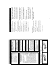
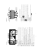
4 3 2 1 Actual Recording Speed Alarm Takes Place Timer Recording Actual Recording Speed Alarm Takes Place Timer Recording Actual Recording Speed Alarm Takes Place Timer Recording Actual Recording Speed Alarm Takes Place Manual or Externally Triggered Recording diagrams below. Alarm Normal Normal 28 Normal Alarm Alarm Normal Normal Normal Alarm NOTE: The status of recording operations when an alarm takes place are shown in the 4.
to switch between decoding and to the left to view the recorded video in the reverse for the picture-by-picture mode. . to return to the can only function in a forward direction; the other, JOG dial : to display one frame/field of a picture at a time in the forward : 30 * About the location of the buttons, please refer to Page 10 2.1 Front View. to return to the normal speed of playback. time in the backward direction.
“^” and FULL LIST ALARM LIST TIME SEARCH THUMBNAIL SD CARDʳ SEARCH “>” buttons, to flip over a page.) A A A to (1) Press the Search button to enter the search mode. to access the time-setting page. to start searching and displaying the concerned image. 32 HH MM 00 : 00 TIME SEARCH MM DD YEAR 11 / 17 / 2002 * About the location of the buttons, please refer to Page 10 2.1 Front View. FULL LIST ALARM LIST TIME SEARCH THUMBNAIL SD CARDʳ SEARCH for another search.
(Mobile Rack HD). Please take the following steps to proceed. CARD F0000.JPG F0001.JPG F0002.JPG F0003.JPG F0004.JPG F0005.JPG SD JPG FILE and then select the “Yes” to delete the image. 34 * About the location of the buttons, please refer to Page 10 2.1 Front View.
BACKUP ALARM TO HD2 MAIN PAGE REFORMAT HD2 USAGE BACKUP----------------FULL ALARM SELECT DISK SETTING to mark it. and , to highlight BACKUP, select SELECT and and 36 * About the location of the buttons, please refer to Page 10 2.1 Front View. movies. This is not a defect. In such a case, it will disappear by opening the Search menu or starting playing back NOTE: The black back will remain (1/7 of screen from the bottom) after executing HD BACKUP.
VIEW OPERATION LOG MAIN PAGE OPERATION LOG MENU BACKGND BUZZER PASSWORD SETUP PWD DEFAULT SD SETUP VERSION SYSTEM Operate Display Setup Search 11 14 Enter Monitor T-rec A-rec DISK REV STOP REC PLAY PAUSE 38 * About the location of the buttons, please refer to Page 10 2.1 Front View. buttons again.
MAIN PAGE SET REC RATE : 20 F/S : BEST : REWRITE : OFF : ON REC SETTING REC RATE REC QUALITY DISK FULL AUDIO MULTIPLEXER MAIN PAGE ALARM REC ENABLE : OFF : 20F/S : BEST : OFF : NO : 0 SEC : OFF ALARM SETTING ALM OPERATION REC RATE REC QUALITY AUDIO ALM TYPE ALM DURATION PRE- ALARM are 5 different record speeds you can select from: 50F/S (50 fields per second), 25F/S, 17F/S, 10F/S, 40 * About the location of the buttons, please refer to Page 10 2.1 Front View.
48KB 32KB 21KB 16KB Basic Alar m activated Duration Duration Alar m deactivated Alar m r ecor ding Alar m deactivated Alar m r ecor ding Reset 42 LIVE images may be interrupted at the time of Alarm-out. NOTE: Recording may be interrupted at the time of Alarm-in or Alarm-out. Alar m activated N on-Stop D uration Set ting options: 0 SEC, 30SEC, 1 MIN, 5 MIN, 10 MIN, and NON-STOP. This option allows users to set alarms for a certain duration.
PAGE PAGE TIMER REC ENABLE MAIN CLOCK REC ENABLE TIMER : SET : OFF : SET MAIN PAGE SET RS232 / RS485 ID : 01 : ON : ON : OFF : OFF : SET COMM SETTING COMM ID RS232 RS485 NET ENABLE NET DHCP NET IP FTP SETTING START END 12:00-18:00 START END S :06:00-16:00 REC SCHEDULE 44 END S :06:00-18:00 START 00:00-00:00 START END REC SCHEDULE automatically combine the two time-period settings into one combined time-period setting.
: 01 : ON : ON : OFF : OFF : SET MAIN PAGE SET FTP ON / OFF FTP might not work correctly. 46 or if the interval between ALARM OUT and IN is too short in ALARM REC setting, NOTE: If the interval between REC and the following REC is too short in ALL REC setting,ʳ When the alarm input is not used, please set it to ALL REC. NOTE: When the alarm input is used, please set REC SETTING of FTP to ALARM REC. ALL REC: To record all the recorded video. ALARM REC: Only to record the alarm-event recorded video.
DISK REFORMAT/CLEAR MAIN PAGE : HD 1 2 : REC : FULL DISK SETTING REFORMAT HD 2 USAGE BACKUP 2: BACKUP.) function has to be proceeded with when the HD 2 USAGE option is set to Clears out all the data stored in HD 2, which is set to backup purpose only. (This Clears out all the data stored in HD 1 and HD 2. Used for data backup only, which will not be part of regular recording hard-disk drive. 48 SELECT: Duplicates a particular recorded video from HD1 to HD2.
50 not be changed in the factory default setting. This option allows you to reload the factory default setting. Please do note that the password can DEFAULT: OFF: Disables it. ON: Enables it. When this option is on, user must pass the password check before entering the setup menu. SETUP PWD: the pre-set password (or the standard password “9999”). NEW PASSWORD: Enter a 4-digit-number password of your choosing which will replace setting) to access the password setting system.
= 0x20 Src ID End Code= 0x4f Command 52 = 0x06 Request System State = 0x02 Request Time/Set Time = 0x01 Handshake = 0x02 Second Category ʳ ʳ ʳ ʳ ʳ ʳ Main Category = 0x01 ʳ Keys and Signals = 0x41 = 0x01 Lead Code Dest ID parameters>,, ..,} , < Dest ID >, < Src ID >, , , {
1 3 6 7 15 23 STATE_REC STATE_PLAY STATE_SETUP STATE_SEARCH STATE_BACKUP STATE_NET_PLAY 17 0F 07 06 03 01 00 HEX Mode.
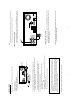
56 9. Push the carrier body further into the mobile rack until fully inserted. 8. Slide the carrier body back in the mobile rack. 57 11. Lock the Key. 6. Place the hard-disk drive inside mobile rack, Use four of the provided screws. 7. Place the top cover back to the carrier body by sliding forward to secure. 10. Push the active-handle inward. 5. Attach the interface connector and the power connector to the drive.
GOTO CLOCK / TIMER PAGE RECORD ALARM CLOCK / TIMER COMMUNICATION DISK SYSTEM PAGE TIMER REC ENABLE MAIN CLOCK REC ENABLE TIMER CLOCK / TIMER MAIN MENU MAIN PAGE ALM OPERATION REC RATE REC QUALITY AUDIO ALM TYPE ALM DURATION PRE- ALARM ALARM REC ENABLE 58 : 20 F/S : BEST : REWRITE : OFF : ON : SET : OFF : SET : OFF : 20F/S : BEST : OFF : NO : 0 SEC : OFF ALARM SETTING SET REC RATE MAIN PAGE REC RATE REC QUALITY DISK FULL AUDIO MULTIPLEXER REC SETTING GOTO ALARM PAGE RECORD ALARM CLOCK /
KEY UNLOCKED n1 OF n2 ITEMS PROGRESS n3 % BACKUP COMPLETE HD2 SPACE NOT ENOUGH NO RECORD FOR BACKUP BACKUP INCOMPLETE 7 8 9 10 11 12 DISK ATTACHED 21 22 NOT PRESENT SAVE TO DISK SAVE TO Fnnn. JPG SAVE OK SD CARD WRITE PROTECT WAIT . . .
Install the Network Viewer in your PC network speed. 62 NOTE: The maximum refresh rate on live mode (REC or STOP) is 2F/S. It depends on the show the pictures and a message will be displayed. NOTE: When the Alarm Operation is ON, The image software (Network Viewer) doesn't document. configured in your computer.
access to certain functional operations of the device via the network. (See the sample 64 Device title and image display area. Displays the title of each connected device and the time/day information of each displayed image on the top blue bar. Connected devices display box. This box indicates the title and IP address of all connected devices. Press to leave the Network Viewer program. Press to open the device setting page to add more devices for viewing.
Function Buttons Description 66 Image display area. Displays the images of each camera and the title and time/date information on the top blue bar. Double click the image to view a full screen of the camera. Split-Screen display function bar. This allows you to display the selected device in multi-format screens of 1, 2x2, 3x3, and 4x4. This allows you to search a recorded video kept in the HDD of the device. Enter the MONTH/DAY/YEAR HOUR: MINUTE you wish to search and click GO to proceed.
to enter the following sample screen. 2. Press images between 1 - 99. 68 Otherwise, VR-601 overwrites the images between 100 - 1,000 while leaving the NOTE: Please change the recording folder if the number of images will exceed 1,000. section to proceed. box on the right-hand side. To view a saved image, please follow the instructions in the next 69 3. Click the PRINT tag to get a displayed image printed out from a printer. selected folder. Each file will be displayed for 2 seconds on the screen.
3000 12-02-02 12:20:55 12-02-02 13:30:33 01-30-03 16:00:34 : : : 02-03-03 16:00:56 2999 3000 HD1 1 2 12-02-02 12:20:55 01-30-03 16:00:34 : : : 02-03-03 16:00:56 02-08-03 17:30:58 3000 LISTS played continuously. 70 END of HDD. In this place, the images should not be new index at the time returning to the TOP from the In the rewrite recording mode, the DVR will generate a overwritten recorded data Previously overwritten.
Connect to WAN (INTERNET) PIN Assignment TX + TX RX + Not Connected Not Connected RX Not Connected Not Connected 12345678 RJ-45 socket OUT TO MONITOR FROM MUX MAIN MONITOR IN AUDIO OUT IN ETHERNET 10/100 RJ-45 RS-485 RS-232 ALARM SD Card I/O DC12V , and to proceed. : 01 : ON : ON : ON : ON : SET SET ETHERNET DHCP MAIN PAGE COMM ID RS232 RS485 NET ENABLE NET DHCP NET IP FTP SETTING COMM SETTING , to highlight NET DHCP; select ON.
74 z Click the Start Menu from your computer, and point to the Settings/Control panel. Follow the instructions below to install the TCP/IP communication program into your computer. 12.3 TCP/IP Communication Software contact a qualified MIS professional or your ISP. network address. If you have any questions regarding these settings, please first two sets of numbers of the DVR IP address must be the same as the as the network address.
76 Æ connection works properly. If not, please contact your ISP provider. z Before processing the DVR installation in a WAN, please make sure the Internet z Select TCP/IP, and then click Properties. z Click Start Æ Settings Æ Control Panel Æ Network. 12.5 TCP/IP Configuration setting installation, the PC will be restarted. During the installation, you will be requested to insert the windows CD-ROM. After 12.
connection. 78 z If you receive a response as in the sample screen below, you have successfully made the contact your dealer. repeating steps 1 to 5. If you still can’t establish the connection after rechecking, please successfully established.
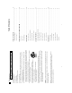
SLDX16C DM RMX-4CD RMX-16CD DPX9 DPX16 MX4016CD-x VCMD-5016 CBR-16eZX MULTIview16CS MPX-CD92P MPX-CD163 PANASONIC PROVIDEO PROVIDEO ATV ATV PELCO ENEO KALATEL AVE SANYO SANYO Channel PAL PAL PAL PAL PAL PAL PAL PAL 16CH 9CH 16CH 16CH 16CH 16CH 16CH 9CH NTSC 16CH NTSC 4CH NTSC 16CH NTSC 16CH NTSC 16CH NTSC 16CH NTSC 16CH NTSC 16CH NTSC 4CH NTSC 16CH NTSC 9CH NTSC 16CH NTSC 9CH NTSC 16CH N/P COLOR COLOR COLOR COLOR COLOR COLOR COLOR COLOR COLOR C
ªWhen sending the "TIME SEARCH" command, please make sure to send the "STOP" command just before sending it. "TIME SEARCH" command (P.54) RS-232 & RS-485 ªThe Playback picture reaches at the END of recorded data in HDD with key lock mode, it will continuously play back in short period near Data end and it will not stop. In such a case, please send the "STOP" command. Operate in the Key Lock mode (P.53, P.66) RS-232, RS-485 or NetViewer ªPlease operate off and on after changing the IP address.