VS-DT2000[US-UW]_Cover1.
VS-DT2000[US-UW]_Warning.fm Page 1 Thursday, April 4, 2002 4:34 PM Warnings, Cautions and Others Avisos, precauciones y otras notas Advertências, precauções e outras notas CAUTION To reduce the risk of electrical shocks, fire, etc.: 1. Do not remove screws, covers or cabinet. 2. Do not expose this appliance to rain or moisture. PRECAUCIÓN Para reducir riesgos de choques eléctricos, incendio, etc.: 1. No extraiga los tornillos, los cubiertas ni la caja. 2.
VS-DT2000[US-UW]_Warning.
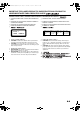
VS-DT2000[US-UW]_Warning.fm Page 3 Thursday, April 4, 2002 4:34 PM Caution: Proper Ventilation To avoid risk of electric shock and fire, and to prevent damage, locate the apparatus as follows: 1. Top: No obstructions and open spacing. 2. Sides/ Front/ Back: No obstructions should be placed in the areas shown by the dimensions below. 3. Bottom: Place on the level surface. Maintain an adequate air path for ventilation by placing on a stand with a height of 10 cm or more.
VS-DT2000[US-UW]_Warning.fm Page 4 Thursday, April 4, 2002 4:48 PM CAUTION ■ About the Internal Cooling Fan This unit (CA-VSDT2000) includes an internal cooling fan, so as to allow for high-power operation within a small space. This fan comes on when the sound level is set high, and may also come on even at low sound levels if the internal temperature rises. To ensure effective fan operation, please leave at least 1 cm clearance on each side of the unit.
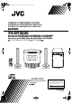
VS-DT2000[US-UW]_EN.book Page 1 Friday, March 8, 2002 3:09 PM English Introduction Thank you for purchasing the JVC Compact Component System. We hope it will be a valued addition to your home, giving you years of enjoyment. Be sure to read this instruction manual carefully before operating your new stereo system. In it you will find all the information you need to set up and use the system. If you have a query that is not answered by the manual, please contact your dealer.
VS-DT2000[US-UW]_EN.book Page 2 Friday, March 8, 2002 3:09 PM English Table of Contents Introduction ........................................................................................................ 1 Features...............................................................................................................................................1 How This Manual Is Organized..........................................................................................................1 WARNINGS.....
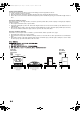
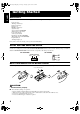
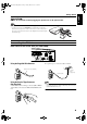
VS-DT2000[US-UW]_EN_1.fm Page 3 Tuesday, April 2, 2002 2:16 PM English Getting Started Accessories Make sure that you have all of the following items, which are supplied with the System.
VS-DT2000[US-UW]_EN.book Page 4 Friday, March 8, 2002 3:09 PM English Getting Started CAUTION: • Make all connections before plugging the System into an AC power outlet. (Only if you install the Center Unit vertically) • To place the Center Unit vertically, the Stand and Legs must be attached. (See page 8.) To make connections, let the cords pass in the holes of the Stand as shown in the diagram before attaching the Stand and Legs.
VS-DT2000[US-UW]_EN.book Page 5 Friday, March 8, 2002 3:09 PM English Getting Started Connecting the AM Antenna Rear Panel of the Center Unit (CA-VSDT2000) SPEAKERS ANTENNA FM (75 ) COAXIAL L R SPEAKER IMPEDANCE 4 CD DIGITAL OUT 16 SUB WOOFER AM LOOP MD/AUX OUT IN AM EXT AC IN AM loop antenna (Supplied) ANTENNA FM (75 ) COAXIAL AM LOOP AM EXT Outdoor single vinylcovered wire (not supplied) Attach the AM loop to its base by snapping the tabs on the loop into the slot in the base.
VS-DT2000[US-UW]_EN.book Page 6 Friday, March 8, 2002 3:09 PM English Getting Started CAUTION: • Make all connections before plugging the System into an AC power outlet. • Handling the speakers As this is a precision instrument, handle it carefully so as to protect it from shocks. Connecting the Speakers (SP-VSDT2000) These speakers are exclusively for this system. Using with other devices will damege the speakers. 1. Open each of the terminals to connect the speaker wire leads. 2.
VS-DT2000[US-UW]_EN.book Page 7 Friday, March 8, 2002 3:09 PM English Getting Started Attaching the Spacers Attach the supplied spacers to the bottom of the powered subwoofer (SP-PW2000) to protect the cabinet, prevent slipping, and absorb the cabinet vibration. Peel off the backing from a spacer and attach it.
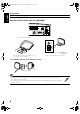
VS-DT2000[US-UW]_EN.book Page 8 Friday, March 8, 2002 3:09 PM Connecting an MD Recorder, etc (Digital Output) Remove the cap and connect an optical digital cord (not supplied) between the System’s CD DIGITAL OUT terminal and the input terminal of the MD recorder, etc. You can record the digital output signal from the System’s CD Player to the MD recorder, etc. Cap MD recorder, etc.
VS-DT2000[US-UW]_EN_1.fm Page 9 Wednesday, March 13, 2002 9:41 AM English Getting Started Installing the Equipment on the Wall The Center Unit and Speakers can be attached to a wall. CAUTIONS: Attachment to a wall • The Center Unit weighs approximately 4.3 kg. When its buttons are operated, an additional force will be applied to it in the downward direction. Therefore, sufficient care must be taken when attaching to a wall to prevent any accidents caused by the Center Unit’s falling off the wall.
VS-DT2000[US-UW]_EN.book Page 10 Friday, March 8, 2002 3:09 PM English Getting Started Example of attachment (Speakers) The speakers can be attached to a wall. Attach the bracket (supplied) to the wall using two screws (not supplied) and place the Speaker onto the bracket. Then, use the wing bolt (supplied) to fix the Speaker firmly to the bracket. Wall Screws (not supplied) Bracket (supplied) Wing bolt (supplied) • Do not place anything on top of the Center Unit.
VS-DT2000[US-UW]_EN.book Page 11 Friday, March 8, 2002 3:09 PM English Getting Started Now you can plug the AC power cord into the wall outlet, and your System is at your command! Before operating, verify that the display shows the clock. If malfunctions may occur, reconnect the power cord. Changing the Display and Control Buttons Settings You can change the direction of the characters and symbols on the display and the assignment of the functions to each control button on the Unit.
VS-DT2000[US-UW]_EN.book Page 12 Friday, March 8, 2002 3:09 PM Using the Remote Control The Remote Control makes it easy to use many of the functions of the System from a distance of up to 7 m away. The remote sensor at which you need to point the Remote Control differs depending on whether the Unit is placed vertically or horizontally.
VS-DT2000[US-UW]_EN.book Page 13 Friday, March 8, 2002 3:09 PM English Basic Operations Operation indicators STANDBY/ON 1 2 Panel 3 PLAY MODE 4 5 6 7 8 9 REPEAT FM MODE 10 +10 BASS TREBLE TREBLE BASS % indicator SET MD/AUX DISPLAY COLOR CANCEL FM/AM DISPLAY DIMMER COLOR CLOCK /TIMER OPEN/ CLOSE SLEEP SOURCE PRESET VOL VOL +/– DIMMER VOLUME +/– VOLUME Illumination COMPACT COMPONENT SYSTEM Turning the Power On and Off Turning the System On Press the % button.
VS-DT2000[US-UW]_EN.book Page 14 Friday, March 8, 2002 3:09 PM Changing the Color (COLOR) Tone Control (BASS/TREBLE) (Using the Remote Control) You can change the color of the illumination on the Unit. (Using the Remote Control) You can control the tone by changing the bass and treble. 1 2 Press the % button to turn on the System. Press the COLOR button on the Remote Control. BASS Control You can adjust the bass level (low frequency range level) between –5 and +5.
VS-DT2000[US-UW]_EN.book Page 15 Friday, March 8, 2002 3:09 PM English Using the Powered Subwoofer STANDBY/ON indicator VOLUME PHASE INPUT (LOW-LEVEL) INPUT (HIGH-LEVEL) VOLTAGE SELECTOR POWER Operating the Powered Subwoofer Presetting the Volume You need to preset the volume level of this speaker (SPPW2000) to match those of the main speakers (SPVSDT2000).
VS-DT2000[US-UW]_EN.book Page 16 Friday, March 8, 2002 3:09 PM English Using the Powered Subwoofer INPUT Terminals The Subwoofer has the following INPUT terminals. INPUT(LOW-LEVEL): Usually, the LEFT/MONO terminal is connected to the SUBWOOFER terminal of the Center Unit with the supplied signal cord. (See page 7.) When the Center Unit CA-VSDT2000 is not used (Using other equipment) If an amplifier etc.
VS-DT2000[US-UW]_EN.book Page 17 Friday, March 8, 2002 3:09 PM English Using the Tuner PRESET+ STANDBY/ON Number Buttons 1 2 4 5 3 6 7 8 9 PLAY MODE REPEAT FM MODE 10 +10 BASS TREBLE +10 SOURCE FM MODE SET PRESET VOL SET MD/AUX CANCEL SOURCE FM/AM FM/AM DISPLAY DIMMER COLOR CLOCK /TIMER OPEN/ CLOSE VOL +/– Band display, Frequency display, Preset channel SLEEP VOLUME STEREO MONO FM mode indicators * When the System is in use, the display shows other items as well.
VS-DT2000[US-UW]_EN.book Page 18 Friday, March 8, 2002 3:09 PM ● Auto Tuning If you press and hold the 4 or ¢ ( or ) button for one second or more, the frequency changes down, or up, automatically until a station is found. OR ● Preset Tuning using the Remote Control (Possible only after presetting stations) Select the desired preset number using the Number buttons on the Remote Control. (For the preset number more than 10, press the +10 button then the Number button.
VS-DT2000[US-UW]_EN_2.fm Page 19 Tuesday, April 9, 2002 5:36 PM Panel STANDBY/ON Number buttons 1 2 4 5 3 6 7 8 9 PLAY MODE REPEAT FM MODE 10 +10 BASS TREBLE PLAY MODE REPEAT +10 SOURCE PRESET VOL SET MD/AUX CANCEL SET FM/AM DISPLAY DIMMER COLOR CLOCK /TIMER OPEN/ CLOSE SLEEP Track number, Playing time, Preset number VOLUME OPEN/ CLOSE PROGRAM RANDOM ALL Play mode indicators * When the System is in use, the display shows other items as well.
VS-DT2000[US-UW]_EN_2.fm Page 20 Wednesday, March 13, 2002 9:42 AM To Select a Track or Passage within a Track CAUTION: • DO NOT try to open or close the Panel by hands as it will be damaged. Press the OPEN/CLOSE button on the Remote Control to open or close the Panel. • DO NOT try to insert another CD when a CD has been already loaded on the Unit. Doing so will damage the CDs and the Unit. • DO NOT apply any shock to the Panel when it is open. • DO NOT clean the Panel when it is open.
VS-DT2000[US-UW]_EN.book Page 21 Friday, March 8, 2002 3:09 PM English Using the CD Player Programming the Playing Order of the Tracks (Using the Remote Control) You can program the playing order of the tracks. ■ You can program up to 32 tracks in any desired order including the same tracks. ■ You can only make a program when the CD Player is stopped. 1 2 3 4 Insert a CD. Press the 7 button to stop the CD. Press the PLAY MODE button on the Remote Control until the “PROGRAM” indicator lights up.
VS-DT2000[US-UW]_EN.book Page 22 Friday, March 8, 2002 3:09 PM Random Play Child Lock (Using the Remote Control) The tracks will play in no special order when you use this mode. • To enter Random Play mode, stop playback first. You can prevent the unwanted CD ejection by locking. • Before proceeding, check the position of the ¢ button on the Unit, then turn off the System. 1 2 Press the PLAY MODE button on the Remote Control until the “RANDOM” indicator lights. Press the 3/8 button.
VS-DT2000[US-UW]_EN.book Page 23 Friday, March 8, 2002 3:09 PM English Using External Equipment STANDBY/ON 1 2 3 PLAY MODE 4 5 6 7 8 9 REPEAT FM MODE 10 +10 BASS TREBLE SET MD/AUX CANCEL MD/AUX SOURCE FM/AM DISPLAY DIMMER COLOR CLOCK /TIMER OPEN/ CLOSE SLEEP PRESET VOL SOURCE VOLUME Listening to External Equipment You can listen to external equipment such as MD recorder, cassette deck or other auxiliary.
VS-DT2000[US-UW]_EN.book Page 24 Friday, March 8, 2002 3:09 PM English Using the Timers STANDBY/ON 1 2 3 PLAY MODE 4 5 6 7 8 9 REPEAT ON time, OFF time, Source, Volume FM MODE 10 +10 BASS TREBLE SET SET MD/AUX CANCEL SLEEP CLOCK /TIMER FM/AM DISPLAY DIMMER COLOR CLOCK /TIMER OPEN/ CLOSE SLEEP Timer indicator SLEEP indicator SLEEP VOLUME * When the System is in use, the display shows other items as well. For simplicity, we show here only the items described in this section.
VS-DT2000[US-UW]_EN.book Page 25 Friday, March 8, 2002 3:09 PM English Using the Timers Setting the Daily Timer 2 Setting the OFF time (Example: 13:30). (Using the Remote Control) Once you have set the Daily Timer, the timer will be activated at the same time every day. 1. Press the SET button. The hour digit of the OFF time blinks on the display. (The same time as the ON time will be automatically set.) The Timer indicator ( ) on the display shows that the Daily Timer you have set is in effect.
VS-DT2000[US-UW]_EN.book Page 26 Friday, March 8, 2002 3:09 PM 6 Before turning off the System, prepare the music source selected in step 3. TUNER: Tune in to the desired station. CD: Insert a CD. (Playback will start from the first track at Timer on.) 7 Press the % button to turn off the System. In standby mode, you can see the Timer indicator ( ) on the display. • When the timer turns on, the Timer indicator starts blinking and the prepared source in step 6 will be played.
VS-DT2000[US-UW]_EN_3.fm Page 27 Friday, April 5, 2002 9:45 AM English Care And Maintenance Handle your CDs carefully, and they will last a long time. Compact Discs • Only CDs bearing this mark can be used with this System. However, continued use of irregular shape CDs (heart-shape, octagonal, etc.) can damage the System. • Do not stick a paper tape or a seal on the reading side or the label side. If you do so, the CD may not be unloaded, or the System can be damaged.
VS-DT2000[US-UW]_EN.book Page 28 Friday, March 8, 2002 3:09 PM • If you are having a problem with your System, check this list for a possible solution before calling for service. Symptom No sound is heard. • If you cannot solve the problem from the hints given here, or the System has been physically damaged, call a qualified person, such as your dealer, for service. Possible Cause • Connections are incorrect, or loose. Action • Headphones are connected. • Check all connections and make corrections.
VS-DT2000[US-UW]_EN.book Page 29 Friday, March 8, 2002 3:09 PM English Specifications CA-VSDT2000 Amplifier Speaker Specifications (each unit) SP-VSDT2000 38 W (19 W + 19 W) at 4 Ω (Max.
VS-DT2000[US-UW]_EN.book Page 30 Friday, March 8, 2002 3:09 PM English Specifications Dimensions for Installation (CA-VSDT2000) Vertical Position (On the wall) 325 mm PHONES COMPACT COMPONENT SYSTEM (With Legs) PHONES 301.5 mm 105.5 mm 140 mm Horizontal Position 86 mm PHONES C O M P A C T C O M P O N E N T S Y S T E M 325 mm 237 mm Design and specifications are subject to change without notice.
VS-DT2000[US-UW]_Cover4.fm Page 31 Tuesday, April 9, 2002 9:46 AM Mains (AC) Line Instruction (not applicable for Europe, U.S.A., Canada, Australia, and U.K.) Instrucción sobre la línea de la red (CA) (no aplicable para Europa, EE.UU., Canadá, Australia, ni el Reino Unido) Instrução sobre a linha tronco da rede elétrica (CA) (não aplicável para Europa, E.U.A., Canadá, Austrália e Reino Unido) SP-PW2000 CA-VSDT2000 H V DISP.