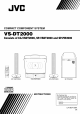
JVC COMPACT COMPONENT SYSTEM VS.DT2000 Consists of CA-VSDT2000, SP.VSDT2000 and SP.PW2000 oooQ QOQ_ QGO6 oooo SP-VSDT2000 DIGITAL CA-VSDT2000 SP-VSDT2000 SP-PW2000 AUDIO INSTRUCTIONS For Customer Use: Enter below the Model No. and Serial No. which are located either on the rear, bottom or side of the cabinet. Retain this information for future reference. Model No. Serial No.
Warnings, Cautions Caution -- (5/I switch ! (CA-VSDT2000) Disconnect the mains plug to shut the power off completely (the (5/I goes off). The (5/I switch in any position does not disconnect the mains line. • When the unit is on standby, the (5/I lights red. • When the unit is turned on, the operation lamps light red. The power can be remote controlled.
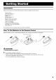
Thank you for purchasing the JVC Compact Component System. We hope it will be a valued addition to your home, giving you years of enjoyment. Be sure to read this instruction manual carefully before operating your new stereo system. In it you will find all the information you need to set up and use the system. If you have a query that is not answered by the manual, please contact your dealer. Features Here are some of the things that make your System both powerful and simple to use.
Introduction ........................................................................................................ Features ............................................................................................................................................... How This Manual Is Organized .......................................................................................................... WARNINGS ..............................................................................................
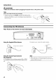
Accessories Make sure that you have all of the following items, which are supplied with the System. Power Cord (1) AM Loop Antenna (1) Remote Control (1) Batteries (2) FM Wire Antenna (1) Signal Cord (1) Spacers (4) (for SP-PW2000) Stand (1) (for Center Unit) Legs (2) (for Stand) Screw (1) (for Stand) Brackets (2) (for SP-VSDT2000) Wing Bolts (2) (for SP-VSDT2000) Paper Pattern (1) If any of these items are missing, How Match To Put the polarity contact Batteries your dealer immediately.
Getting Started CA U TION: • Make all connections before plugging the System into an AC power outlet. (Only if you install the Center Unit vertically) • To place the Center Unit vertically, the Stand and Legs must be attached. (See page 8.) To make connections, let the cords pass in the holes of the Stand as shown in the diagram before attaching the Stand and Legs.
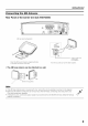
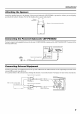
Getting Started Connecting the AM Antenna Rear Panel of the Center Unit (CA-VSDT2000) AM loop antenna (Supplied) LOOP AM Outdoor single vinylcovered wire (not supplied) Attach the AM loop to its base by snapping on the loop into the slot in the base. the tabs Turn the loop until you have the best reception. • The AM loop antenna can be attached to a wall. Screw (not supplied) • If the AM loop antenna wire is covered with viny!, remove the vinyl by twisting it as shown in the diagram.
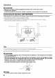
Getting Started .d_ CA UTION: • Make all connections before plugging the System into an AC power outlet. • Handling the speakers As this is a precision instrument, handle it carefully so as to protect it from shocks. Connecting These speakers the Speakers are exclusively (SP-VSDT2000) for this system. Using with other 1. Open each of the terminals to connect the speaker wire leads. 2. Connect the speaker cords to the Speaker terminals of the Unit.
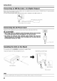
Getting Started Attaching the Spacers Attach the supplied spacers to the bottom of the powered subwoofer (SP-PW2000) and absorb the cabinet vibration. Peel off the backing from a spacer and attach it. Spacer \ © to protect the cabinet, prevent slipping, ? /supplied/ __ /_ Connecting Connect Powered the Powered a signal cord (supplied) Subwoofer.
Getting Started Connecting an MD Recorder, etc (Digital Output) Remove the cap and connect an optical digital cord (not supplied) between the System's CD DIGITAL input terminal of the MD recorder, etc. You can record the digital output signal from the System's CD Player to the MD recorder, etc. _ _ OUT terminal and the MD recorder, etc.
Getting Started Installing The Center the Equipment Unit and Speakers on the can be attached Wall to a wall. CA U TIONS: Attachment to a wall • The Center Unit weighs approximately 4.3 kg. When its buttons are operated, an additional force will be applied to it in the downward direction. Therefore, sufficient care must be taken when attaching to a wall to prevent any accidents caused by the Center Unit's falling off the wall.
Getting Started Example of attachment (Speakers) The speakers can be attached to a wall. Attach the bracket (supplied) to the wall using two screws (not supplied) and place the Speaker Then, use the wing bolt (supplied) to fix the Speaker firmly to the brakcet. onto the bracket. Wing bolt (supplied) • Do notplace anything on top of the Center UniL Doing so may cause the Center Unit to fail, causing malfunctioning and/or injury. • Do not climb onto the Center Unit or hang from it.
Getting Started Now you can plug the AC power cord into the wall outlet, and your System is at your command! Before operating, verify that the display shows the clock. If malfunctions may occur, reconnect the power cord. Changing the Display and Control Buttons Settings You can change the direction of the characters and symbols on the display and the assignment of the functions to each control button on the Unit. Change the settings depending on whether the Unit is placed vertically or horizontally.
Getting Started Using the Remote Control The Remote Control makes it easy to use many of the functions of the System from a distance of up to 7 m away. The remote sensor at which you need to point the Remote Control differs depending on whether the Unit is placed or horizontally. vertically Remote sensor (when the Unit is placed horizontally) • The maximum operating distance becomes short when the Panel is opened. Remote sensor (when the Unit is placed vertically) • Make sure that the "DISP.
Operation © indicators Panel _b/I VOL +!- © / I Illumination Turning the Power On and CD-in Off The CD-in indicator lights while using the Tuner or external equipment and does not light during CD operations. in the mode it was Adjusting (DIMMER) Turning the System Off • Some power is always consumed even though turned off (called Standby Mode). [-I_ DIMMER Display ] Press the DISPLAY button consumption in standby on the Remote the System is turned off.
Basic Operations Changing the Color (COLOR) Tone (Using the Remote Control) You can change the color of the illumination on the Unit. 1 Press the (!)/I button to turn on the System. 2 Press the COLOR button on the Remote Control. "RANDOM COLOR" setting of your choice. The color changes --I_RANDOM COLOR
II1 - STANDBY/ON indicator POWER 000000000000000 0000000000000000 @ Adding the Richness to the Bass (PHASE) Operating Subwoofer the Powered If you want to add the richness more to the bass, press the PHASE button to set it either in the "-- REVERSE" position or the "11 NORMAL" position, whichever can add the richness to the bass. Presetting the Volume You need to preset the volume level of this speaker (SPPW2000) to match those of the main speakers (SPVSDT2000).
Using the Powered Subwoofer INPUT Terminals The Subwoofer has the following INPUT terminals. INPUT(LOW-LEVEL): Usually, the LEFT/MONO cord. (See page 7.) terminal is connected to the SUBWOOFER When the Center Unit CA-VSDT2000 terminal of the Center Unit with the supplied is not used (Using other equipment) If an amplifier etc. to be connected does not have the SUB WOOFER OUT terminals, minals will be connected to the LINE OUT-RIGHT and LEFT terminals of that unit.
PRESET+ ,/-+10 -- FM MODE -- S ET --> SOURCE _1_ m ),,IH Band display, Frequency display, Preset channel I [ FM 105.50MHz ] FM mode indicators * When the System is in use, the display shows other items as well. For simplicity, we show here only the items described in this section. You can tuned listen to FM and AM in manually, automatically, stations. or from Stations preset can be memory storage.
Using the Tuner Presetting Stations (Using the Remote Control) You can preset up to 30 FM stations tions. To Change Mode and up to 15 AM sta- • Preset numbers may have been set to factory test frequencies prior to shipment. This is not a malfunction. You can preset the stations you want into memory by following one of the presetting methods below. Manual Presetting /I 1 \ I / STORED \ / .[ or AM FM = 30, Select a band by pressing button. 2 Press the I-<< or _ (^ I \ the FM/AM or v) butto
Panel J _/I _ • _.411I,,IH _ Track number, Playing time, Preset number I CD 20 50" 45 I P_O_AM_ANDOM _ ALLI ] I Play mode indicators * When the System is in use, the display shows other items as well. For simplicity, we show here only the items described in this section. You can use Normal, Random, Program or Repeat Play. Repeat Play can repeat all the tracks or just one of the tracks on the CD.
Using the CD Player To Select a Track or Passage within a Track CA U TIONS: • DO NOT try to open or close the Panel by hands as it will be damaged. Press the OPEN/CLOSE button on the Remote Control to open or close the Panel. • DO NOT try to insert another CD when a CD has been already loaded on the Unit. Doing so will damage the CDs and the Unit. • DO NOT apply any shock to the Panel when it is open. • DO NOT clean the Panel when it is open.
Using the CD Player Programming of the Tracks the Playing Order • To stop playing, (Using the Remote Control) You can program the playing order of the tracks. • You can program up to 32 tracks cluding the same tracks. • You can only make a program stopped. 1 • You can skip to a particular I<1<1or I_1_1 button during in any desired order in- when the CD Player is program Program press the • button track by pressing Play. the once.
Using the CD Player Random Child Play (Using the Remote Control) The tracks will play in no special mode. • To enter Random 1 Play mode, order when you use this stop playback first. indicator 2 until the "RANDOM" "LOCKED" lights, To Release are played in random order. To skip a track during playback, press the I_1_1 button to jump to the next track in the random sequence. Press the I<1<1button to jump back to the start of a track being played.
©@@0 MD/AUX-- SOURCE Listening to External You can listen to external equipment cassette deck or other auxiliary. Equipment such as MD recorder, • First make sure that the external equipment connected to the System. (See page 7.) 1 Press the MD/AUX "MD/AUX" appears is properly button. the System's Equipment Source You can record the System's source to external equipment which is connected to the MD/AUX-IN/OUT or CD DIGITAL OUT terminals MD recorder, etc.
ON time, OFF time, Source, Volume I I 7:': 00 'ON ] Timer indicator MI_ m s_TP e -- ooo@ SLEEPindicator --SLEEP CLOCK__ /TIMER * When the System is in use, the display shows other items as well. For simplicity, we show here only the items described in this section. The timers let you control Setting (Using the the Remote listening functions automatically. 4 Press the SET button. The minute the display.
Using the Timers Setting the Daily 2 Setting the OFF time (Example: 13:30). Timer (Using the Remote Control) Once you have set the Daily Timer, vated at the same time every day. the timer The Timer indicator (_) ) on the display ly Timer you have set is in effect. will be acti- shows that the Dai- • When the Timer Indicator activated. (_) ) is displayed, • When the Timer Indicator is deactivated. (_) ) is not displayed, 1. Press the SET button.
Using the Timers 6 Before turning off the System, prepare the music source selected in step 3. TUNER: CD: Tune in to the desired Insert a CD. (Playback track at Timer on.) station. will start from the first 7 Press the VII button to turn off the System. In standby mode, on the display. you can see the Timer indicator (_) ) Setting the SLEEP Timer (Using the Remote Control) Use the Sleep Timer to turn the System off after a certain number of minutes when it is playing.
Handle your CDs carefully, and they will last a long time. Compact Discs OIGIn'AL AUDIO x@ x@ • Only CDs bearing this mark can be used with this System. However, continued use of irregular shape CDs (heart-shape, octagonal, etc.) can damage the System. • Do not stick a paper tape or a seal on the reading side or the label side. If you do so, the CD may not be unloaded, or the System can be damaged. • Remove the CD from its case by holding it at the edges while pressing the case's center hole lightly.
• If you are having a problem with your System, check this list for a possible solution before calling for service. • If you cannot solve the problem from the hints given here, or the System has been physically damaged, call a qualified person, such as your dealer, for service. Possible Cause Symptom No sound is heard. • Connections are incorrect, or loose. • Check all connections and make • Headphones corrections. (See pages 4 to 8.) • Disconnect the headphones. are connected.
CA-VSDT2000 Amplifier Output Power Input Sensitivity/Impedance MD/AUX IN Output Sensitivity/Impedance MD!AUX OUT CD DIGITAL OUT (Optical out) Speaker terminals Subwoofer out Phones 38 W (19 W + 19 W) at 4 t) (Max.
JVC VICTOR @EN COMPANY OF JAPAN, LIMITED (_ 0402MNMIDEJEM