LIVE STREAMING CAMERA Detailed User Guide GV-LS2 U LYT2488-002A
Table of Contents Camera.............................................................. 5 Pantilter............................................................. 7 Configuring the Camera Settings Appropriate for Your Needs................8 Example 1: Worried about your pet staying at home alone................................................... 8 Example 2: Record birds coming to a feeder on the balcony.................................................... 9 Example 3: Live-stream a performance in a studio....
Using the Unit Alone.............................32 Turning on/off the power.................................. 32 Removing........................................................ 29 Starting/Stopping recording............................. 32 Charging.......................................................... 29 Controlling from a Web Browser..........33 Connecting an External Mic.................30 Logging in........................................................ 33 Connecting to the camera..........
Verifying the Accessories If any item is missing or damaged, please contact your place of purchase or customer support. Introduction Camera Camera. Pantilter Attach it to the camera before use. Can be panned (right/left) or tilted (up/down) remotely from a computer or mobile terminal. ( ➭ page 25) AC Adapter UIA324-12 Connect it to the camera or pantilter when using with AC power. ( ➭ page 12) * Attach an AC cord and a conversion cable. AC cord Use it when connecting the AC adapter.
Component Names and Functions Camera Back 5 1 6 3 PLUG IN POWER 4 1 2 RESET DIRECT WLAN Introduction Front MIC DC 7 LAN(OFF) AV ETHERNET 8 5 3 4 2 1 Internal mic (stereo) Transmits/Records sounds coming through this mic when no external mic is connected. 2 Lens Be careful not to touch directly or let anything come into contact. 3 LED light Works as a light in dark places. Turn on/off from a browser. ( ➭ page 36) 4 Information lamp Can be lit up to indicate the recording status, etc.
Top Bottom Introduction 1 2 3 4 1 Hot shoe Mount camera accessories. * Do not mount any accessories when the pantilter is attached. 2 Record button Starts recording. To stop, press this button again. The lamp indicates the current status. Off: Recording not in progress Blinking: Recording in progress Blinking quickly (for 2 seconds): Recording error 3 WPS button Press and hold to connect wirelessly (Wi-Fi) in WPS mode. ( ➭ page 20) The lamp indicates the current status.
Pantilter When using the pantilter, connect the AC adapter, AV cord, and external mic to the pantilter. Back Introduction Front 1 2 8 1 2 3 MIC PLUG IN POWER AV EXTEND DC 456 7 1 Power button Press and hold to power on. To power off, press and hold this button again. 2 Power lamp Indicates the pantilter status. Off: Powered off Lit up: Powered on Blinking: Pantilter error Bottom 1 Tilt lock (TILT LOCK) Face the pantilter right in front and slide the knob to the left to lock it.
Configuring the Camera Settings Appropriate for Your Needs The unit can be used for various purposes. See the following examples for how to set up and use appropriately: Introduction Power? • AC adapter ( ➭ page 12) • Battery ( ➭ page 29) Connection method? • Wired connection ( ➭ page 20) • Wireless (Wi-Fi) connection ( ➭ page 21) Recorded data? • Save to an SD card. ( ➭ page 17) • Transmit in high quality.
Example 2: Record birds coming to a feeder on the balcony. Setup Setting • Do not connect to the computer or access point (router). • Only records when the scene is changed. ("AUTO REC") ( ➭ page 36) Introduction • Use the battery as the camera is set on a high shelf by the window. ( ➭ page 29) • Insert an SD card to save recorded data. ( ➭ page 28) Use • After recording, transfer the recorded data to a computer and then play it. ( ➭ page 37) Example 3: Live-stream a performance in a studio.
Flow of Connection/Setup Connect the unit to the computer, and configure the appropriate settings on a browser. Starting shooting 1 Connect the camera to your computer via the supplied LAN cable. ( ➭ page 11) To set up the camera, first connect it to your computer. Preparation 2 Connect the AC adapter. ( ➭ page 12) Connect the supplied AC adapter when the connections are complete. 3 Access the unit from a browser to configure the appropriate settings.
Connecting the Camera to Your Computer To set up the camera, first connect it to your computer. Required operating environment Browser: Internet Explorer 9 or later 1 Attach the LAN cable to the unit. PLUG IN POWER RESET DIRECT WLAN MIC DC LAN(OFF) AV ETHERNET Preparation 2 Connect the camera to your computer via the LAN cable. 3 Set the network mode switch to "LAN(OFF)".
Connecting the AC Adapter Connect the supplied AC adapter to the DC connector of the camera. CAUTION • Be sure to use the supplied AC adapter. Use of another AC adapter may cause a malfunction. • Turn off the power before connecting/disconnecting the AC adapter.
Configuring the Camera Settings Appropriate for Your Needs Access the unit from your computer to set the network, streaming, etc. Required operating environment Browser: Internet Explorer 9 or later Configuring the initial settings To configure the settings for the first time after purchase, connect the camera directly to your computer via a LAN cable. 2 Press and hold the power button to power on. The record button starts blinking. Wait until it stops blinking and off.
Changing the settings after changing the connection destination To change the settings after changing the connection destination ( ➭ page 20), visit the following address.
Configuring the Camera Settings This section describes the settings necessary to use the unit. For the "MANAGE" settings not mentioned on these pages, refer to page 46 . Adjusting the clock 4 Click the "SET" button. Adjust the internal clock. The time can be displayed when videos are transmitted. 1 Select "COMMON SETTINGS" in "MANAGE". If the sub settings are not displayed, click "+" on the left of "MANAGE". Preparation 2 Click the "SET" button on the right of "CLOCK ADJUST".
Setting the user name and password 4 Click the "SAVE" button. The user name and password set at the time of purchase are common across all the units of this model. They should be changed as soon as possible for security reasons. 1 Select "COMMON SETTINGS" in "MANAGE". If the sub settings are not displayed, click "+" on the left of "MANAGE". The new user name and password have been set. Preparation 2 Click the "UPDATE" button on the right of "CHANGE ADMINISTRATOR USER/PASSWORD".
Selecting the Format of Images to be Output/Saved This unit can output up to two lines of images. Set the output method and image quality appropriate for your needs. For the "NETWORK" settings not mentioned on these pages, refer to page 41 . 1 Select "STREAM SETTINGS" in "NETWORK". If the sub settings are not displayed, click "+" on the left of "NETWORK". 3 Select an option from "MAX FRAME RATE (MotionJPEG)". Preparation 2 Select an option from "STREAM 1/STREAM 2".
Allowing You to Connect from Outside (Monitoring Setting) To view images from outside, you normally need to obtain a global IP address or URL to access from a browser. Entering the account of our DDNS service allows you to set these easily. Obtaining a DDNS account Access our website from a computer or smartphone for provisional registration. Preparation 1 Visit the following URL to register an account provisionally. https://dd3.jvckenwood.com/user/ Enter your e-mail address for the user name.
Adding a camera driver's user To access to the unit using the camera driver ( ➭ page 39), you need to set the user name and password beforehand. (Up to four users can be registered.) Initial setting: USERNAME "root", PASSWORD "password". They should be changed as soon as possible for security reasons. * Multiple users cannot view simultaneously. Enter 1 to 32 characters for the user name, and 8 to 32 characters for the password. (1 byte alphanumeric characters and symbols only) 4 Click the "SAVE" button.
Changing the Connection Destination If necessary, change the connection destination to the access point (wireless LAN router). Establishing a wired connection to the access point 1 Select "WIRED NETWORK" in "NETWORK". If the sub settings are not displayed, click "+" on the left of "NETWORK". CAUTION Preparation • For how to set the access point, refer to the instruction manual, etc. of the access point.
Connecting to the access point wirelessly (Wi-Fi) Using the WPS function Searching and connecting to the access point 1 Select "WIRELESS NETWORK" in "NETWORK". Connect to the access point equipped with the WPS function easily. 1 Press and hold the power button to power off. 2 Disconnect the LAN cable that connects the camera to your computer. 3 Set the network mode switch to "WLAN". 5 Enable the WPS function of the access point. (Example) Press the "WPS" button.
4 Enter "PASSWORD". Connecting manually 1 Select "WIRELESS NETWORK" in "NETWORK". 5 Click the "SAVE" button. Preparation If the sub settings are not displayed, click "+" on the left of "NETWORK". 2 Click the "MANUAL" button. The settings to be configured on a browser have been complete. Close the browser, and shutdown the computer. 6 Press and hold the power button to power off. 3 Enter the information, and click the "SAVE" button. 7 Disconnect the LAN cable that connects the camera to your computer.
Connecting to a computer directly (Wi-Fi Direct) Using the WPS function 1 Press and hold the power button to power off. 2 Disconnect the LAN cable that connects the camera to your computer. 3 Set the network mode switch to "DIRECT". 4 Press and hold the power button to power on. The record button starts blinking. Wait until it stops blinking and off. 6 Press and hold the "WPS" button. When the "WPS" button stops blinking and stays lit, the connection is complete.
Connecting Multiple Cameras To connect multiple cameras, configure the following settings. 1 Select "MONITORING SETTINGS" in "NETWORK". If the sub settings are not displayed, click "+" on the left of "NETWORK". 4 Select "COMMON SETTINGS" in "MANAGE". If the sub settings are not displayed, click "+" on the left of "MANAGE". Preparation 2 Change "PORT NUMBER" (1 to 65535) so that the numbers do not duplicate between the cameras. 5 Change "CAMERA NAME" so that the names do not duplicate between the cameras.
Attaching the Pantilter The supplied pantilter allows you to pan (move horizontally) and tilt (move vertically) the camera using your computer or smartphone. • • • • • Remove all cables before attaching the pantilter. When using the pantilter, connect the AC adapter, AV cord, and external mic to the pantilter. Confirm the hole position on the bottom to attach it. Attach the camera firmly, making sure that it is not lifted. Hold the pantilter, not the camera, when carrying it.
Connecting the AC adapter Removing the pantilter Connect the supplied AC adapter to the DC connector of the pantilter. • Be sure to unlock the pantilter before connecting the AC adapter. ( ➭ page 7) • Remove all tape from the pantilter. PLUG IN POWER RESET DIRECT WLAN To use the camera alone ( ➭ page 32), remove the pantilter. 1 Loosen the camera fixing screw sufficiently.
Establishing a wired connection When establishing a wired connection to the computer or access point, attach the supplied LAN cable as follows. Required operating environment Browser: Internet Explorer 9 or later 1 Set the network mode switch to "LAN(OFF)". PLUG IN POWER RESET DIRECT WLAN MIC DC LAN(OFF) AV ETHERNET Preparation DIRECT WLAN LAN(OFF) • If the network mode switch is set to [DIRECT] or [WLAN], the LAN terminal cannot be used.
Inserting/Removing an SD Card Insert a separately purchased SD card to save recorded data to the card. The saved data can be deleted/ downloaded from a browser. • Turn off the power before inserting/removing the SD card. • The saved data can be played back by Windows Media Player 12 ( ➭ page 37). Inserting Compatible SD cards Insert the card straight with the terminal side facing right. • Make sure that the write protect switch of the SD card is not set to LOCK (writing protected).
Attaching/Removing the Battery The camera can run with the battery power only. When the battery (BN-VG139U) (sold separately) is attached, videos can be transmitted/recorded even in places where the AC adapter cannot be used. • The battery cannot be used when the pantilter is attached. • Turn off the power before attaching/removing the battery.
Connecting an External Mic Connect an external mic to record external sounds. Connect a commercially available mic to the MIC terminal of the pantilter when it is attached, or of the camera when not attached. • • • • • Use the plug-in power type. Do not use microphone with L-shaped connectors. Turn off the power before connecting/disconnecting the mic. Without an external mic, the internal mic can record ambient sounds. When the sounds are too loud or too low, change the "MIC LEVEL SETTING".
Connecting the AV Cord Connecting to a TV or the like via an AV cord (sold separately) allows you to view images being recorded/ transmitted even without a computer or mobile terminal. Connect a separately purchased AV cord to the AV connector of the pantilter when it is attached, or of the camera when not attached. • Turn off the power before connecting/disconnecting the AV cord. • Use the f3.5 mm 4-pole mini plug type. Do not use an L-shaped mini plug.
Using the Unit Alone Insert an SD card and attach the battery, so you can carry and use the unit as a normal video camera. Set whether to save recorded videos to the SD card or stream them wirelessly. ( ➭ page 41) Turning on/off the power Turning on the power Press and hold the power button. The record button starts blinking. Wait until it stops blinking and off. Turning off the power Press and hold the power button again. The power button turns off.
Controlling from a Web Browser You can control the unit from a web browser without installing additional software. To watch a video via a network, "MONITORING SETTINGS" ( ➭ page 18) must be set. Required operating environment OS: Windows 7 Browser: Internet Explorer 9 or later Logging in Use "USERNAME" and "PASSWORD" of the administrator ( ➭ page 16). 1 If the power is not turned on, press and hold the power button to power on. The record button starts blinking. Wait until it stops blinking and off.
Controlling the camera ("MONITOR" tab) Control the camera and view images on the "MONITOR" tab. 1 4 5 6 2 7 3 1 Tab Switch the display. Use "MONITOR" Control the camera and view streamed images. "FILE MANAGEMENT" Delete video files stored on the SD card or download them to your computer. ( ➭ page 37) "STATUS" Check the message history. ( ➭ page 38) * When you are logged in as a viewer, you can view the "MONITOR" tab only. 2 Control panel Control the camera/pantilter.
rough guide). 3 Zoom ratio Displays the current zoom ratio. 4 5 6 7 8 4 Recording status Indicates the camera status. STANDBY: Recording not in progress REC: Recording in progress 5 Recording mode Recording mode: UXP, XP, SP, EP 6 SD card Indicates that an SD card can be used. 7 Remaining recording time Indicates the remaining recording time. 8 Power status Indicates the power status.
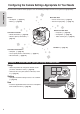
Configuring the camera settings Change the camera settings. * The screen can only be displayed when you are logged in as an administrator. 1 2 3 4 5 6 7 8 9 0 = Use 1 "AUTO REC" Turn on/off the "AUTO REC" function that records only when the scene is changed. When the setting is changed to "ON", the following settings are automatically changed: "BRIGHTNESS ADJUST": "AUTO" "DIS": "OFF" "LIGHT": "OFF" While set to ON, you cannot start recording, pan/tilt the camera, or change the "GAIN UP" setting.
Managing files stored on the SD card ("FILE MANAGEMENT" tab) Use the "FILE MANAGEMENT" tab to transmit/delete files stored on the SD card. * The screen can only be displayed when you are logged in as an administrator. 3 1 4 2 3 "DELETE" To delete a video file, first click this button. Then click a thumbnail to display the delete confirmation screen. To delete, click "YES". 2 Thumbnail After clicking "TRANSFER" or "DELETE", click the thumbnail of the target file to be transferred or deleted.
Checking the message history ("STATUS" tab) Use the "STATUS" tab to check error messages or currently connected users. The "STATUS" tab is categorized into "CAMERA", "NETWORK", and "LOG IN USER". * The screen can only be displayed when you are logged in as an administrator. "CAMERA" "LOG IN USER" 1 2 1 2 1 Tab Switch the display. 2 "ERROR INFO" Displays the error history of the camera/pantilter. "NETWORK" Use 1 2 1 "ERROR INFO" Displays the network error history.
Using "JVC CAM Control" The supplied "JVC CAM Control" allows you to control multiple cameras. Required operating environment Operating System: Windows® 7 Home Premium (32-bit/64-bit, Pre-install, with SP1) CPU: Intel® CoreTM 2 Duo 2 GHz or higher (Intel® CoreTM 2 Quad 2.66 GHz or higher when using MPEG-2 TS(HD)) RAM: 2 GB or more Installing "JVC CAM Control" 1 Insert the supplied software CD-ROM into the CD/DVD drive of your computer.
Using the Mobile Terminal You can operate the camera intuitively on the touch panel of a smartphone/tablet terminal. In addition, the camera can be panned/tilted by moving the tablet terminal. Names of Apps for mobile terminals Installing the App for mobile terminals There are three types of Apps for mobile terminals: For smartphone (Android OS), for Android tablet, and for iOS. Download the appropriate App. 1 Download the software appropriate for your environment. • Smartphone (Android OS 2.
Setting Item List If you log in as an administrator on a browser of your computer, you can change the settings. The settings are categorized into "NETWORK", "CAMERA/PAN TILTER", and "MANAGE". To display the setting item list, "Configuring the Camera Settings Appropriate for Your Needs" (page 13) "NETWORK" Configure the settings for the network and streaming on "NETWORK". "NETWORK" is categorized into "WIRED NETWORK", "WIRELESS NETWORK", "MONITORING SETTINGS" and "STREAM SETTINGS".
Setting for connecting to an access point (wireless LAN router) wirelessly (Wi-Fi). "REGISTERED ACCESS POINT" Lists up to eight access points that were connected before. "SELECT" button Select an access point from "REGISTERED ACCESS POINT" and click this button to change the connection destination. "DELETE" button Select an access point from "REGISTERED ACCESS POINT" and click this button to delete the connection information.
"MONITORING SETTINGS" Change the settings for connecting via a network. 1 2 3 4 5 1 "USER (JVC CAM driver)" Lists the registered users. For details, refer to page 19 . "ADD" button Up to four camera driver's users can be added. "UPDATE" button Update the user name and password of the registered user. "DELETE" button Delete the registered user. 2 "PORT NUMBER" Change the port number assigned to the unit, e.g. if the unit conflicts with other devices.
"STREAM SETTINGS" Format for transmitting/recording. 1 2 3 1 "STREAM 1 / STREAM 2" Select the quality of images to be streamed from the following: "MotionJPEG(640x360)/NONE" "MPEG-2 TS (720x576)/MotionJPEG (640x360)" "MPEG-2 TS (1920x1080)/MotionJPEG (640x360)" 2 "MAX FRAME RATE (MotionJPEG)" Select "15fps" or "7.5fps" for the maximum frame rate of MotionJPEG. 3 "SAVE" button After changing the above settings, click this button to save the changes.
"CAMERA/PAN TILTER" Configure the settings for the camera and pantilter on "CAMERA/PAN TILTER". Categorized into "CAMERA SETTINGS" and "PAN TILTER SETTINGS". "CAMERA SETTINGS" "PAN TILTER SETTINGS" Change the camera settings. Change the pantilter settings. 1 2 3 4 5 6 1 2 3 7 1 AUTO ZOOM RESET Select "OFF" or "ON" for the function that resets the zoom ratio automatically if no operation is performed for 5 minutes.
"MANAGE" Configure the settings for the administrator and hardware on "MANAGE". Categorized into "COMMON SETTINGS", "MEDIA MANAGEMENT" and "TURN OFF CAMERA". "COMMON SETTINGS" "MEDIA MANAGEMENT" Change the settings of the administrator and camera. Format the SD card. 1 3 2 4 5 7 6 1 "CAMERA NAME" Enter 1 to 15 characters for the camera name displayed during viewing.
"TURN OFF CAMERA" Click the "EXEC" button to turn off the camera's power remotely. CAUTION * The power cannot be turned on remotely.
Troubleshooting Connection Problem Check Refer to • Check the remaining battery. The battery is no longer charged if already full. page 35 • Charge the battery. • Check if the connector is dirty. If it is dirty, clean it with a cotton swab or the like. page 29 The SD card cannot be inserted. • Check the orientation of the card. page 28 The power does not turn on when the pantilter is attached. • Check if the camera is attached firmly to the pantilter.
Setup Problem Check Refer to You cannot connect to the unit even when you are at home. (You are requested to enter the URL.) • Check if the wireless (Wi-Fi) connection is complete. • Check if the connection destination of a computer or mobile terminal is set to the camera. • Power on the unit, computer and mobile terminal again, and retry. page 20 You entered the URL, but the unit cannot be found.
Problem Information 50 Check Refer to The access point (wireless LAN router) cannot be found. • Retry to connect in a better reception environment. If there is a long distance or interference or if there is a microwave or another wireless device nearby, the communication speed may slow down or the connection may not be established. • If a stealth SSID is assigned to the access point, turn it off. • If there are many access points, the target access point may not be found. In this case, set up manually.
Use Problem Check Refer to Shooting stopped automatically. • Shooting stops automatically as it cannot be performed for 12 or more consecutive hours. • The unit stops automatically to protect the circuit when the temperature rises. Turn off the unit, wait for a while, and turn it on again. – A recorded file cannot be found. • No file is saved if the playback time is less than one second. – Brightness changes irregularly.
Problem Camera images do not appear./ Camera images are gone. Check • Camera images disappear if no operation is performed for 120 hours. Perform one of the following so that images reappear: ––Press the shooting button. (Shooting starts.) ––Operate the pantilter. ––Press the reload button. ––Disconnect and then connect the AV cable. • Do not connect the AV cable to the camera and pantilter simultaneously.
Error messages Message Check Refer to • To record, insert an SD card into the camera. page 28 NEED TO FORMAT MEMORY CARD. • If a card is used for the first time after purchase or has been used with other devices, it may need to be formatted with this unit. page 46 THIS CARD CANNOT BE USED FOR RECORDING OR EDITING ON THIS CAMERA • Format the card. page 46 INSUFFICIENT AVAILABLE SPACE • Available space is insufficient. Delete unnecessary files.
Message Information 54 Check Refer to INCORRECT PASSWORD • The two passwords entered on the change password screen are different. Enter the same password in the two fields. – USE AC ADAPTER • When updating the firmware, connect the AC adapter. page 12 NO UPDATES AVAILABLE • Check if the update file is written in the correct folder on the SD card. – UPDATE CORRUPTED • Retrieve the firmware update file, and copy it to the SD card.
Lamp Status List Record WPS POWER (Pantilter) Turns off – – – Power off (Charging) Blinks slowly – – – Power on (Activating) Lights Blinks – – Power on (Activation completed) Lights – – – Wireless/Wired disabled *1 – – Turns off – Attempting connection *2 – – Blinks slowly – Connection established *3 – – Turns off – Attempting WPS – – Blinks – No access (Unrelated to the existence of media) – Turns off – – Shooting impossible – Blinks quickly (only for 2 seco
Resetting to the factory settings Reset all the unit settings to factory default. 1 Select "COMMON SETTINGS" in "MANAGE". If the sub settings are not displayed, click "+" on the left of "MANAGE". 2 Click the "EXEC" button on the right of "FACTORY PRESET". Information 56 3 To execute, click the "EXEC" button. Deleting (Resetting) the connection information Delete the connection information stored in the unit. Press and hold the reset button of the camera for three seconds with the AC adapter connected.
Updating the firmware The firmware updater is sometimes uploaded to our website for operational improvement. (There is no notice on our website until the firmware updating program is provided.) http://www3.jvckenwood.com/dvmain/support/ download/index.html 1 Copy the update file to an SD card, and insert the card into the unit. Do not copy other files. 2 Select "COMMON SETTINGS" in "MANAGE". If the sub settings are not displayed, click "+" on the left of "MANAGE".
Specifications Camera Power supply Using the AC adapter: DC 12 V, Using a battery pack: DC 3.6 V Power consumption 5.6 W (when using the pantilter), Rated current consumption: 2 A Dimensions (mm) 73 x 48 x 90 (2 7/8'' x 1 15/16'' x 3 9/16'') (W × H × D) Mass Approx. 229 g (0.
Stream output format Stream 1 Format 1 Format 2 Format 3 Stream 2 Video JPEG (640x360) Audio LPCM 16 kHz 16 bit 1 ch System MPEG-2 TS Video H.264 Main Profile (720x576) JPEG (640x360) Audio AAC 48 kHz 16 bit 2 ch LPCM 16 kHz 16 bit 1 ch System MPEG-2 TS Video H.
©2012 JVC KENWOOD Corporation 0812HO-MW-VM