
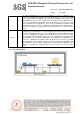
Schematics

SGS-CSTC Standards Technical Services Co., Ltd.
Shenzhen Branch
Report No.: SZCR210402034305
Page: 20 of 843
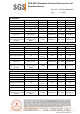
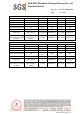
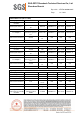
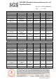
7.1.4 Measurement Procedure and Data
1) The mains terminal disturbance voltage test was conducted in a shielded room.
2) The EUT was connected to AC power source through a LISN 1 (Line Impedance Stabilization
Network) which provides a 50ohm/50μH + 5ohm linear impedance. The power cables of all other
units of the EUT were connected to a second LISN 2, which was bonded to the ground reference
plane in the same way as the LISN 1 for the unit being measured. A multiple socket outlet strip was
used to connect multiple power cables to a single LISN provided the rating of the LISN was not
exceeded.
3) The tabletop EUT was placed upon a non-metallic table 0.8m above the ground reference plane.
And for floor-standing arrangement, the EUT was placed on the horizontal ground reference plane,
4) The test was performed with a vertical ground reference plane. The rear of the EUT shall be 0.4 m
from the vertical ground reference plane. The vertical ground reference plane was bonded to the
horizontal ground reference plane. The LISN 1 was placed 0.8 m from the boundary of the unit under
test and bonded to a ground reference plane for LISNs mounted on top of the ground reference
plane. This distance was between the closest points of the LISN 1 and the EUT. All other units of the
EUT and associated equipment was at least 0.8 m from the LISN 2.
5) In order to find the maximum emission, the relative positions of equipment and all of the interface
cables must be changed according to ANSI C63.10 on conducted measurement.
Remark: LISN=Read Level+ Cable Loss+ LISN Factor