
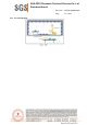
Schematics

SGS-CSTC Standards Technical Services Co., Ltd.
Shenzhen Branch
Report No.: SZCR210402034305
Page: 38 of 843
7.8.4 Measurement Procedure and Data
a. For above 1GHz, the EUT was placed on the top of a rotating table 1.5 meters above the ground at
a 3 meter fully-anechoic chamber. The table was rotated 360 degrees to determine the position of the
highest radiation.
b. The EUT was set 3 meters away from the interference-receiving antenna, which was mounted on
the top of a variable-height antenna tower.
c. The antenna height is varied from one meter to four meters above the ground to determine the
maximum value of the field strength. Both horizontal and vertical polarizations of the antenna are set
to make the measurement.
d. For each suspected emission, the EUT was arranged to its worst case and then the antenna was
tuned to heights from 1 meter to 4 meters (for the test frequency of below 30MHz, the antenna was
tuned to heights 1 meter) and the rotatable table was turned from 0 degrees to 360 degrees to find
the maximum reading.
e. The test-receiver system was set to Peak Detect Function and Specified Bandwidth with Maximum
Hold Mode.
f. If the emission level of the EUT in peak mode was 10dB lower than the limit specified, then testing
could be stopped and the peak values of the EUT would be reported. Otherwise the emissions that
did not have 10dB margin would be re-tested one by one using peak or average method as specified
and then reported in a data sheet.
g. Test the EUT in the lowest channel, the middle channel, the Highest channel.
h. The radiation measurements are performed in X, Y, Z axis positioning for Transmitting mode, and
found the X axis positioning which it is the worst case.
i. Repeat above procedures until all frequencies measured was complete.
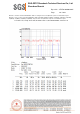
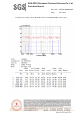
Remark:
1. Level= Read Level+ Cable Loss+ Antenna Factor- Preamp Factor
2. Scan from 18GHz to 40GHz, the disturbance above 18GHz was very low. The points marked on
above plots are the highest emissions could be found when testing, so only above points had been
displayed. The amplitude of spurious emissions from the radiator which are attenuated more than
20dB below the limit need not be reported.
3. As shown in this section, for frequencies above 1GHz, the field strength limits are based on
average limits. However, the peak field strength of any emission shall not exceed the maximum
permitted average limits specified above by more than 20 dB under any condition of modulation. For
the emissions whose peak level is lower than the average limit, only the peak measurement is shown
in the report.
4. The disturbance above 18GHz were very low and the harmonics were the highest point could be
found when testing, so only the above harmonics had been displayed.