
Installation Manual

* FREE K&N
®
decal To register your warranty, please see us online at knlters.com/register. FREE K&N
®
decal *
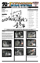
INSTALLATION INSTRUCTIONS
Continued
ROAD TESTING:
38. It will be necessary for all K&N
®
high ow intake
systems to be checked periodically for realignment,
clearance and tightening of all connections.
Failure to follow the above instructions or proper
maintenance may void warranty.
37. Reconnect the vehicle’s negative battery cable.
Double check to make sure everything is tight and
properly positioned before starting the vehicle.
• 1455 CITRUS ST., P.O. BOX 1329, RIVERSIDE, CA., U.S.A. 92502 • TECH SERVICE 800-858-3333 • FAX 951-826-4001
• e-mail: tech@knlters.com
®
• WWW: http://www.knlters.com
®
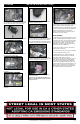
1. Start the engine with the transmission in neutral
or park, and the parking brake engaged. Listen for
air leaks or odd noises. For air leaks secure hoses
and connections. For odd noises, find cause and
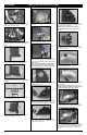
repair before proceeding. This kit will function
identically to the factory system except for being
louder and much more responsive.
2. Test drive the vehicle. Listen for odd noises or
rattles and x as necessary.
3. If road test is ne, you can now enjoy the added
power and performance from your kit.
4. K&N Engineering, Inc., requires cleaning the
intake system’s air lter element every 100,000
miles. When used in dusty or off-road
environments, our lters will require cleaning more
often. We recommend that you visually inspect
your lter once every 25,000 miles to determine
if the screen is still visible. When the screen is no
longer visible some place on the lter element, it is
time to clean it. To clean and re-oil, purchase our
lter Recharger
®
service kit, part number 99-5050
or 99-5000 and follow the easy instructions.
28. Install the provided silicone vent hose onto the
90° vent tting in the K&N
®
intake tube and attach
the open end to the valve cover port as shown.
29. Remove the EVAP tting from the intake hose.
36. Install the K&N
®
air lter and secure with the
provided hose clamp.
NOTE: Do not over tighten the air lter hose
clamp as crush damage to the mass air sensor
housing will occur.
35. Install the 30” long section of edge trim onto
the fresh air plate and heat shield as shown. Some
trimming of the edge trim will be necessary.
34. Pass the hood release cable through the
grommet installed into the K&N
®
fresh air plate and
then secure the fresh air plate to the heat shield
and mounting bracket with the provided hardware.
Reinstall the hood release cable to the hood latch.
30. Install the EVAP tting into the intake tube and
then connect the EVAP vent line.
33. Install the provided 7/8”OD grommet into the
K&N
®
fresh air plate as shown.
31. Reconnect the mass air sensor electrical
connection.
32. Disconnect the hood release cable from the
hood latch.
19583D
10/17/13