
Installation Manual


69-3518
1. Turn off the ignition and disconnect the negative
battery cable.
NOTE: Disconnecting the negative battery cable
erases pre-programmed electronic memories.
Write down all memory settings before
disconnecting the negative battery cable. Some
radios will require an anti-theft code to be
entered after the battery is reconnected. The
anti-theft code is typically supplied with your
owner’s manual. In the event your vehicles
anti-theft code cannot be recovered, contact an
authorized dealership to obtain your vehicles
anti-theft code.
TO START:
™
FORD
2013-14 Focus ST
L4-2.0L Turbo
TOOLS NEEDED:
NOTE: FAILURE TO FOLLOW INSTALLATION INSTRUCTIONS AND NOT USING THE PROVIDED HARDWARE
MAY DAMAGE THE INTAKE TUBE, THROTTLE BODY AND ENGINE.
Description Qty. Part # Description Qty. Part # Description Qty. Part #
A Hose Clamp #48 3 08601
B Hose; 3"ID X 3"L Hump 1 08696
C Bolt; M5-0.8 X 20MM, SS 1 22208
D Washer; 5MM Internal Start Cut 1 07724
E Washer; 5MM Flat, SS 1 08212
F Intake Tube 1 27601TS
G Hose; 3-1/2" To 3"ID X 3"L TPRD 1 084055
H Hose Clamp #56 1 08620
I Bolt; Hex M6-1 X 35MM 1 1-2002
J Washer, 1/4"ID X 5/8" OD-SAE 7 08275
K Bracket; "Z", 69-3518, STL 1 064311
L Washer; 1"D X 1/4 Hole Fender 1 08160
M Washer; 1" X .300 X .100 Rubber 1 21685
N Nut; 6MM Nylock, Hexhead,SS 1 07512
O Bolt; M6 X 1.00 X 16MM, SS 3 07730
P Washer; M6 Split Lock Zinc 5 1-3025
Q Edge Trim (26") 1 102488
R Heat Shield 1 073148
S Bolt; 6MM-1.00 X 16MM, SS 2 07812
T Stud; Rubber Mount, M6 X 1 1 02033
U Mount, Plastic Airbox 1 8-186
V Adapter; Universal, 6" Filter 3.5" 1 21512-1
W Hose Clamp #104 1 08697
X Air Filter 1 RU-4600
PARTS LIST:
Flat blade screw driver
Ratchet
Extension
8mm socket
10mm socket
3mm allen key
4mm allen key
10mm wrench
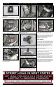
2. Disconnect the pressure sensor electrical
connection.
3. Disconnect the fresh air inlet boot.
4. Loosen the hose clamp securing the intake hose
to the plenum.
5. Remove the air box from the engine
compartment.
NOTE: K&N Engineering, Inc., recommends that
customers do not discard factory air intake.
6. Remove the fresh air duct from the core support
as shown.
7. Install the provided rubber mounted stud into the
inner fender as shown.
8. Install the provided mounting post onto the heat
shield as shown using the provided hardware.
9. Install the lter adapter into the heat shield and
secure with the provided hardware.
A
B
A
A
G
H
V
W
X
O
P
J
K
F
C
D
E
I
J
L
M
Q
J
N
R
O
P
J
J
P
S
J
T
U
P
S