
Installation Manual

69-7002
TOOLS NEEDED:
NOTE: FAILURE TO FOLLOW INSTALLATION INSTRUCTIONS AND NOT USING THE PROVIDED HARDWARE MAY DAMAGE
THE INTAKE TUBE, THROTTLE BODY AND ENGINE.
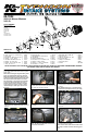
1. Turn off the ignition and disconnect the negative
battery cable.
NOTE: Disconnecting the negative battery cable
erases pre-programmed electronic memories.
Write down all memory settings before discon-
necting the negative battery cable. Some radios
will require an anti-theft coded to be entered
after the battery is reconnected. The anti-theft
code is typically supplied with your owner’s
manual. In the event your vehicles’ anti-theft
code cannot be recovered, contact an autho-
rized dealership to obtain your vehicles anti-
theft code.
TO START:
PARTS LIST:
Description Qty. Part #
™
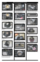
8.Remove the two air lter housing mounting grom-
mets shown.
2. Remove the three bolts that secure the fresh air
intake duct shown. These bolts will be re-used in a
later step.
2009-14 Nissan Maxima
V6-3.5L
Flatblade Screwdriver
Ratchet
Extension
10mm Socket
8mm Socket
7mm Socket
Pliers
10mm Wrench
5mm Allen Wrench
3mm Allen Wrench
3. Remove the fresh air intake duct from the vehicle
as shown.
4. Release the crank case vent hose spring clamp
and then disconnect the crank case vent hose from
the intake tube resonator chamber.
5. Disconnect the mass air sensor electrical
connection.
6. Remove the air box retaining bolt shown.
Note: This bolt is located at the rear of the air
box near the strut tower.
7. Loosen the hose clamp that secures the intake
tube to the air box. Remove the stock air box from
the vehicle.
Note: K&N Engineering Inc. recommends that
customers do not discard the factory air intake.
9. Remove the Stock Intake tube and intake tube
resonator chambers as shown.
Note: Pull the lower intake tube resonator cham-
ber rmly to release it from the mounting grom-
met.
A
B
A
C
E
F
G
H
D
A
K
L
H
S
F
G
H
H
T
G
N
M
O
Q
P
L
Q
R
T
G
N
V
U
W
X
Y
Z
A Hose Clamp #52 3 08610
B Hose; 3-1/4” ID X 2” L Reinforced 1 08690
C Intake Tube 1 27443
D Bolt; M4-0.07 8MM, A/H Cap, SS 2 07733
E Bracket; “L”, STL, TK/PC 1 070113
F Bolt; M6X1.00X12MM, Hex, SS 2 07727
G Washer; 1/4” LOCK, ZN 4 08198
H Washer; 1/4”ID X 5/8”OD - SAE 4 08275
I Hose; 1/2” ID X 7” L 1 08159
J Hose Mender; 1/2” TO 5/8”, Barbed 1 08726
K Edge Trim (20”) 1 102494
L Nut; 6MM Nylock, Hexhead, SS 3 07512
M Heat Shield 1 073114
N Washer; 6MM Flat, SS 2 08269
O Stud; M/F, 1/2”L X 1”W, M6 X 1.00 1 070228
P Washer; 1.25D X. 28 HOL 4 08151
Q Washer; 1” X .300 X .100 Rubber 2 21685
R Stud; M6 X 1, 1” T, M/F 1 02033
S Bracket; 57-3025, L-Bend 1 070952
T Bolt; 6MM-1.00 X 16MM, SS 3 07812
U Edge Trim (35”) 1 102471
V 3.25”id to 3.50”idX2.25”L, tprd 1 084091
W Hose Clamp #56 1 08620
X Adaptor; 57-1530 #380 1 21512
Y Hose Clamp #104 1 08697
Z Air Filter 1 RC-2960