
User manual


16
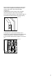
If after having carried out the operation just
described there is still some space left between the
appliance and the kitchen unit, fit the trimming
provided together with the appliance, on the stop
strip (A).
Fig. 4
Open the door and push the appliance against the
side of the kitchen furniture opposite to that of the
appliance hinges.
Fasten the appliance with 4 screws provided in the
kit included with the appliance.
Snap vent grill (C) and hinge cover (D) into position.
Fig. 5
Press in the joint covers between the appliance and
the kitchen unit.
Fig. 6
D265
A
D092
D
C
D305
Apply covers (B) on joint cover lugs and into hinge
holes.
Fig. 7
Position the runners (H) inside the kitchen unit door
as shown in Fig. 8 and mark the position of the
external holes.
After preparing the holes, screw the runners to the
kitchen unit door using 3.5x16 mm screws.
Fig. 8
Open both the appliance door and that of the kitchen
unit to approx. 90°.
Place the little plates over the runners.
Hold the doors of the appliance and the unit
together and mark the holes.
Fig. 9
D096
B
D094
20mm
H
8mm
PR34