
Operation Manual


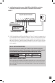


3. Installing the wired rain sensors 3208-HRFS or 3208-HRS into controllers
with pump start/master valve terminal; and without sensor terminals:
FIGURE 2
B. 24-VAC Solenoid Valves with Pump Start Relay (See Figure 2). Locate the common wire to
the solenoid valves and the common wire lead to the coil of the relay that starts the pump.
If these two wires are connected to the “common” terminal on the controller, disconnect
both of them. Twist these two wires together along with one wire from the rain sensor and
secure with a wire nut. Attach the other wire of the rain sensor to the “common” terminal
on the controller.
FOR ALL INSTALLATION METHODS:
Once the rain sensor is mounted, run the wire to the controller, using wire
clips every few feet to fasten it. If an extension to the wire provided is needed,
use the following table to determine the minimum wire gauge needed:
CHECK TO VERIFY CORRECT WIRING
Turn on one zone of the sprinkler system that is visible while you are in reach of the rain
sensor. Manually depress the manual test pin at top of the rain sensor until you hear the
switch “click” off. The sprinkler zone should stop instantly. If it does not, check wiring for
correct installation.
1234
COM
Irrigation System Controller
Wire ConnectorCommon Wire from Valves
To Valves
24 VAC
1234
COM
PUMP/
MV
Irrigation System Controller
Pump Start Relay/
Master Valve
Wire ConnectorCommon Wire from Valves
To Valves
24 VAC
Extension Needed: 25-50 ft. 50-100 ft. 100 ft. or more
then use: 20 AWG 18 AWG 16 AWG
06