8321 Swamp Road Prairieville, Louisiana 70769 USA Tel: (1) 225-673-6100 / Toll Free 800-735-5835 Fax: (1) 225-673-2525 / Toll Free 888-442-1367 Email: service@ktekcorp.com Website: www.ktekcorp.
TABLE OF CONTENTS 1. INTRODUCTION ................................................................................................................ 4 2. OVERVIEW ........................................................................................................................ 5 2.1 Storage Information ......................................................................................................................... 5 2.2 Ambient Temperature ........................................................
TABLE OF CONTENTS (CONTINUED) 9. APPENDICES ................................................................................................................ 23 9.1 APPENDIX A: Sensor Trim ............................................................................................. 23 9.2 APPENDIX B: Additional Special Functions in the CFG2 (Hidden) Menu....................... 24 9.3 APPENDIX C: Linearization ............................................................................................ 26 9.
1.0 INTRODUCTION Thank you for using the K-TEK MT2000 Guided Wave Radar Transmitter. The MT2000 has been designed for ease of use and to offer extensive configuration capabilities. You are urged to review this manual in its entirety prior to use. This will eliminate most installation problems due to improper configuration. We, the K-TEK Family, sincerely hope you receive many years of reliable use from this transmitter and welcome your feedback to consistently improve our products.
2. OVERVIEW 2.1 Storage Information If required, storage prior to installation should be indoors at ambient temperature, not to exceed the following: Temperature range: -40 to 150 degrees F. Humidity: 0 to 100% R.H. non-condensing. 2.2 Ambient Temperature The MT2000 electronics temperature may not exceed 170°F / 77°C. For higher ambient temperatures, a high temperature option extension is required.
2.3.1 Direct Reflect Mode (standard) (cont’d) The measurement principle using TDR is based on the fact that a dielectric constant discontinuity or geometric change will yield a negative pulse having certain amplitude below the baseline. The greater the dielectric constant difference, the greater the negative amplitude of the return signal.
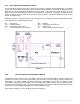
3. INSTALLATION 3.1 Mounting Requirements IMPORTANT: To obtain the best return signal from the product level it is recommended to mount the MT2000 coupler directly into the top of the vessel if the vessel material is metal, or into a metal plate if the vessel is non-metallic. A flat metal surface perpendicular to the probe acts as a “launch plate”, minimizing the loss of microwave energy from dispersion (Figure 3-1).
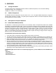
3.2 Shortening of Probe The MT2000 single probe can be cut to length prior to installation. The MT2000 default factory configuration provides a measurement in engineering units with a zero referenced to the bottom of the sensing probe. The top of the probe yields a measurement equal to the probe length (Figure 3.2). 20 mAdc 0Probe in / 0 Length mm URV = Probe Length LRV = 0 in. / 0 mm 4 mAdc Cable Length 0 in. / 0mm Factory Default Configuration 1.
3.3 MT2000 Guided Wave Radar Guidelines (cont’d) Rods: • 1/4”rod 5 ft. max, minimum 3” Dia. Stilling well if provided with stilling well. • 1/2” rod 10 ft. max, minimum 3” Dia. Stilling well if provided with stilling well. • In 2” pipe: 5ft. Max 1/4” or 1/2” rod. Coaxial: • C8 and C9 with rigid rod always fully assembled with sensor well from factory. 3.4 Wiring Install conduit to ½” NPT port and run 18 gauge twisted, shielded pair to housing.
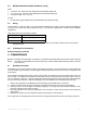
4.1 Quickstart Procedure (cont’d) LRV = 4 mA 0 in. / 0 mm URV= 20mA 300 in. / 7620 mm CAL Raw Counts LTP = 6” HTP = 288” CFG 2100 2565 13272 BLK = 210 Figure 4.1 4.2 Verify Proper Power-Up Apply power to the transmitter and verify that the display comes up and is active. The display update rate is approximately 4 seconds. The current draw should under no case exceed 21 mA and, in the event of a problem, refer to trouble-shooting section. 4.
4.3.1 LCD Menu Operation The LCD display is menu driven, uses the UP, DOWN, and SELECT pushbuttons for navigation. • Press UP or DOWN to scroll through menu options. • Press SELECT to select a menu option. • When changing a variable use SELECT to move between signs or digits.
4.4 Detailed Configuration Parameters 4.4.1 Direct Mode Blanking Menu Note: This section only applies to direct mode measurement. The blanking parameter (BLK) is used to ignore an extended nozzle that would otherwise cause a reflected signal at the top of the probe and result in a high level reading even when no product is in the vessel. For probe configuration 1,2,5,6 or 7 (Appendix G) use the factory default BLK. BLK can be changed by accessing SET followed by the CFG menu (refer to menu chart).
4.4.2 Threshold Level Parameter (THV) and Gain Setting (GS) (cont’d) The following values should be used as starting points: For Mounting Configuration 1,2,3a and 3b, (direct insertion in tank - no stilling well applications, no coaxial probes) with the following dielectric constant: GS THV ≥ 10 2* 1.5* ≥ 3 and < 10 2 1.7 GS THV 4 1.0 4* 1.
4.4.3 Advanced Parameter Settings (cont’d) • KO & KG KO and KG parameters should only be changed during the replacement of an electronic module. Refer to troubleshooting section • LCH For Devices configured to measure 0 at the end of the probe, this value defines the sensitivity of the Latching feature. When this feature is enabled, and the detected signal extends past the end of the probe, the resulting output is “latched” at 0, until the signal is again detected at the end of the probe.
4.4.4 Ultra Low Dielectric (ULD) Mode Configuration Note: Use this method for very low dielectric solids only, when little or no usable signal can be obtained from the product surface. Use in solids measurement applications with 1.3 < DC < 2.0. If the DC is above this 2.0 value please contact the factory for application support. Special calibration of the Trim Points is required. 1. The dielectric constant of the material must be stable and below 2.
4.4.4 Ultra Low Dielectric (ULD) Mode Configuration (cont’d) Coupler If it is not practical to establish a known level in the vessel before commissioning the MT2000 a demo MT2000 with a short probe can be used in a small container of the product to estimate the product dielectric constant with this procedure. If this estimated DC is used, we recommend verifying it later with a known vessel level that is as high as possible.
4.5.5 Bench Calibration of the 4mA & 20mA Points: After the transmitter is configured correctly, a manual bench calibration of the 4mA and 20mA points using hands or targets, can be done as follows. Note: The following applies to single or dual Rod and Cable probes only. Other assemblies such as coaxial probes must be calibrated with products. If the probe is a rod, position it so that it stands clear of any objects (minimum of 6 in. / 152 mm).
4.5.7 Reversing The Output Action Using Actual Level Input • • • • Adjust the level to 50% ( + or - 10% ). • Enter the calibration mode by pressing the UP & DOWN buttons together for 1 second and press the DOWN button for 1 second to set the output at 4.00 mA. Adjust the level to the new SPAN point. • Enter the calibration mode by pressing the UP & DOWN buttons together for 1 second and press the UP button for 1 second to set the output at 20.00 mA. Adjust the level to where the ZERO needs to be set.
5. TROUBLESHOOTING INFORMATION Use a milliamp (mA) meter to measure the output current. When power is applied the output will go to 4.00 mA for at least one (1) second and then to either the measured level or an alarm condition output. If this does not happen the transmitter may not be receiving enough power or the main electronic is defective. Excessive current above 21.00 mA is also an indication of improper power up or defective electronics. 5.1 Valid Current Loop Outputs 21.
5.2 Possible Symptoms (cont’d) SYMPTOM ACTION Raw Counts are 0 and Output is in alarm Raise the Threshold Check probe for presence Decrease blanking No Display Check cables Check for proper supply voltage Check for proper wiring Replace electronics module 21 mA output Unit is in ALRM – check THV, GS (section 4.4.2); check BLK (section 2.3.3.
6.2 Operating Modes The MT2000 transmitter with DE option can be operated in two ways, selectable using the setup menu of the instrument: 1. DE Digital Mode: In this mode the transmitter output is strictly digital and uses the Honeywell DE Protocol, which modulates the loop current On and Off to transmit digital information per above Class Conformance definition. 2. Analog Output Mode: In this mode the Honeywell DE Digital Output is disabled and the transmitter is in a standard 4-20 mA output mode.
8. GLOSSARY OF TERMS EU Engineering Units Display units selection (inches, mm, feet, %, etc.
9. APPENDICES 9.1 APPENDIX A: Sensor Trim Sensor trim is preset at the factory for a specific type of probe, installation and application condition. Re-trimming in the field should not be necessary unless a major change in antenna length (+/- 40%) is required. Low Trim Point LTP and High Trim Point HTP are the points used to define the measuring range of the unit.
The sensor trim is now complete and the LRV has been set to equal 0 and URV has been set to the value of HTP. If other LRV and URV are desired, then proceed to the CAL menu and change LRV and URV accordingly. If the level cannot be moved, the transmitter must be removed for re-trimming. Please contact the factory before trimming to confirm the procedure to follow. Should the trim be suspected of being corrupted, please consult the factory.
9.2 APPENDIX B: Additional Special Functions in the CFG2 (Hidden) Menu (continued) These functions are accessed by pressing the ‘UP’ and ‘DOWN’ buttons together, when the LCD display is on ‘END’ at the end of the CFG menu. Enter the Sensor Trim menu and scroll down to access the following functions: • RNG Range Selection - Select Range 1 for sensors < 100 ft. (30.5 m) and range 2 for sensors ≥ 100 ft. (30.5 m).
9.3 APPENDIX C: Linearization The MT2000’s multi-point linearization system allows improved measurement accuracy along the length of the probe. In particular, this feature can be used to correct non-linearity, which can be seen, typically close to the top and close to the bottom of the sensing probe. In most application, linearization is not required. The MT2000 linearization uses a table of points set up by the user.
9.4 APPENDIX D: Interface Applications It is possible to use an MT2000 to determine the level of an interface but certain requirements must be met: 1. The dielectric constant of the upper liquid must be low (between 2 and 3). 2. The dielectric constant of the lower liquid must be higher than the upper liquid (10 or greater). 3. The interface layer must be contained within a few inches. 4. A means of venting all vapor/gas from the top of the chamber must be available. 5.
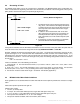
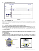
9.5 APPENDIX E: Oscilloscope Use & Setup for Troubleshooting 9.5.1 General Setup • • • • • Connect Channel A to Pin 6 Connect GND to Pin 3 Connect Trigger to External to Pin 4 Set Volts to 500 mV / div Set Time to 50 ųSec / div Your output should resemble this: Pin 6 Return Signal Pin 1 Not used Pin 5 Not used Pin 2 Not used Pin 4 Sync Pulse Pin 3 Ground or Common Figure 9.4 9.5.
9.
9.
9.
9.
9.
9.9 APPENDIX I: Mounting Configurations Flat Plate Or Coupling 1, 2 3a, 3b MINIMUM MAXIMUM DIELECTRIC PROBE CONSTANT LENGTH 1.31 100 ft./30.5 m MINIMUM MAXIMUM DIELECTRIC PROBE CONSTANT LENGTH 1.31 100 ft./30.5 m Permanent Stilling Well 4 MINIMUM MAXIMUM DIELECTRIC PROBE CONSTANT LENGTH 1.7 20 ft./6.1 m 3 30 ft./9.1 m Removable Stilling Well 4 20 ft./6.1 m 1.7 3 20 ft./6.1 m 30 ft./9.1 m 10 40 ft./12.2 m 10 40 ft./12.2 m 10 50 ft./15.2 m 10 50 ft./15.2 m 35 100 ft./30.5 m 35 100 ft.
9.10 APPENDIX J: Warranty Statement 5 YEAR WARRANTY FOR: KM26 Magnetic Liquid Level Gauges; MagWave Dual Chamber System; LS Series Mechanical Level Switches (LS500, LS550, LS600, LS700, LS800 & LS900); EC External Chambers, STW Stilling Wells and ST95 Seal Pots. 3 YEAR WARRANTY FOR: KCAP300 & KCAP400 capacitance switches. BETA Pressure and Temperature Switches have a limited factory guarantee, excluding wetted parts & consumables.