
Instructions / Assembly

4 For Professional Technical Support call 1-844-242-2475
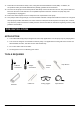
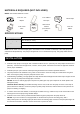
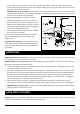
MATERIALS REQUIRED (NOT INCLUDED)
NOTE: Parts shown below not to scale.
1-1/2” to 1-1/4”
adaptor
1-1/2’’ ABS or
PVC Pipe
Thread Tape
1-1/2” check
valve
ABS or PVC
Cement
(to match the
pipe)
1-1/2” 90°
Elbow
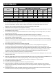
SPECIFICATIONS
Power supply
115V, 60 HZ., 15 Amp Circuit
Liquid temp. range
32°F to 95°F (0°- 35°C)
Discharge size
1-1/2 in. FNPT
Sump basin
Min. 10 in. (254 mm) diameter, 14 in. (356 mm) depth
NOTE: Do not reduce size of discharge pipe or hose below 1-1/4 in. diameter. If discharge is too small, pump will
overheat and fail prematurely. This pump is designed for use in a residential sump only. Only pump water with this
pump.
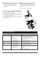
INSTALLATION
1. Install the sump pump in a sump pit with a minimum diameter of 10 in. (254 mm).The sump depth should be 14 in.
(356 mm) . Construct the sump pit of tile, concrete, steel or plastic. Check the local codes for approved materials
and for proper installation.
2. Install the pump in a pit so that the switch operating mechanism has maximum possible clearance.
3. The pump should not be installed on clay, earth or sand surface. Clean the sump pit of small stones and gravel
which could clog the pump. Keep the pump inlet screen clear.
4. Install discharge plumbing. Use rigid plastic and wrap threads with PTFE pipe thread sealant tape. Put pipe into the
quick connector of pump and hand tight plus 1-1/2 turns.
NOTICE: Do not use ordinary pipe joint compound on plastic pipe. Pipe joint compound can attack plastics and
damage the pump.
CAUTION: Risk of flooding. If a flexible discharge hose is used, make sure the pump is secure in the sump to
prevent movement. Failure to secure the pump may allow pump movement, switch interference and prevent the
pump from starting or stopping.
5. To reduce motor noise and vibration, a short length of rubber hose (e.g. radiator hose) can be connected into the
discharge line near the pump using suitable clamps.
6. Install an in-line check valve to prevent backward flow through the pump when the pump shuts off.
NOTICE: If your check valve is not equipped with an air bleed hole to prevent air locking pump, drill a
1/8in.(3.2mm)hole in the discharge pipe just above where the discharge pipe screws into the pump discharge. Be
sure the hole is below the waterline and the check valve to prevent air locks.