
Instructions / Assembly


08
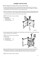
5. Attach the Gas Cylinder Support (L) to the Right Panel (B) and the Left Panel (C) with Bolt (AA) and Washer
(BB) using the Hex Screw Driver (CC), (see Figure 5).
NOTE: DO NOT tighten the screws completely.
Hardware Used:
AA Bolt (M6 x 15) x 4
BB Washer (M6) x 4
CC Hex screw driver x 1
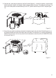
6. Attach the Door (D) to the Upper Beam (J) and the Bottom Beam (K) with Bolt (AA) and Washer (BB) using the
Hex Screw Driver (CC), (see Figure 6).
NOTE: DO NOT tighten the screws completely.
Hardware Used:
AA Bolt (M6 x 15) x 2
BB Washer (M6) x 2
CC Hex screw driver x 1
Hardware Used:
AA Bolt (M6 x 15) x 8
BB Washer (M6) x 8
CC Hex screw driver x 1
CC
AA
BB
CC
AA
BB
CC
AA
BB
Figure 4
Figure 5
Figure 6