
User guide


35
Using the Multi-Inputs
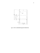
Select the input you wish to display by turning the front panel selector switch. The knob's
index mark indicates the selected input as labeled on the front panel lens.
fig. 21 -- MCD 8000 Front Panel;
The display is normally configured to display the measuring channel output in the numbered
position starting to the right of the display. For example, if you wish to read the output from
channel 4 you will need to set the display switch to `4' which will read the output from the
module 4 positions to the right of the display. Some function card modules contain dual channel
outputs, these modules will count as 2 positions. For example, if you had 2 measuring
channels, a dual RMS->DC converter card (dynamic module -004), and a third measuring
channel in the fourth slot, when the display switch is on channel 4 you will read the RMS
output of channel 2 and if the switch is on channel 5 you will read the measuring channel in
the fourth position to the right of the display. Some modules have no outputs that go to the
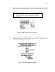
display, these modules count as 0 positions. The following table gives the displayed outputs
and count. The channel numbers are relative to the modules to the left of the function card.
Dash Displayed 1st 2nd
Module number Outputs Position
8200 any 1 ---- ----
8200HT any 1 ---- ----
VC8000 any 0 ---- ----
SP8000 any 0 ---- ----
SC8000 any 1 Summed Output ----
DY8000 -001 2 Ch 1 P-P Ch 1 RMS
DY8000 -002 2 Ch 1 +Peak Ch 2 +Peak
DY8000 -003 2 Ch 1 -Peak Ch 2 -Peak
DY8000 -004 2 Ch 1 RMS Ch 2 RMS
Table 4 -- Displayed Outputs;