Non-contact Displacement Measuring System User’s Manual Copyright © 2013 PART NO: 860525-001 Last Revised: 9/16//2013 Kaman Precision Products A Division of Kaman Aerospace Corporation 217 Smith Street Middletown, CT 06457 www.kamansensors.
TABLE OF CONTENTS PART 1 – INTRODUCTION..........................................................................................................4 PART 2 – CONNECTIONS...........................................................................................................5 PART 3 - FRONT PANEL CONTROLS .......................................................................................6 PART 4 – MENU TREE ..................................................................................................
6.3 2-Point Linear Calibration .................................................................................................16 6.4 6-Point Polynomial Calibration ..........................................................................................17 6.5 21-Point Piecewise Calibration .........................................................................................18 6.6 2-Point Adjustment........................................................................................................
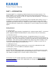
PART 1 – INTRODUCTION The Kaman digiVIT is a revolutionary inductive displacement measuring instrument. The digiVIT simplifies use of a variety of Eddy Current sensors for precision measurements of; displacement, position, vibration, run-out, etc, in typical and difficult applications. The digiVIT is user configurable and adjustable. The digiVIT does not require any special factory setup to work with most inductive sensors.
PART 2 – CONNECTIONS The digiVIT I/O connections are all through a 10 pin removable terminal block. The DigiVIT sensor is connected through an SMA coaxial connector on the opposite side of the enclosure. An RJ45 Ethernet connection is provided for UDP/IP communication. Pin Name 1 +24V 2 3 4 5 6 7 8 9 10 Gnd Vout Gnd Iout Gnd NC IO Relay Relay Function +24V Input @ 0.
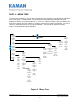
PART 3 - FRONT PANEL CONTROLS The digiVIT can easily be set up using the front panel controls. 1 2 1. Sensor connection (SMA) 3 2. Digital display 4 3. Scroll up pushbutton 4. Scroll down pushbutton 5 5. Escape pushbutton 6 6. Enter pushbutton 7. Ethernet connection (RJ45) 8. I/O screw terminals 7 8 Figure 1 Front Panel Controls Note: Press the Escape pushbutton (#5 in the figure above) momentarily to return to the previous menu tree branch.
PART 4 – MENU TREE The menu tree for digiVIT, accessed by pushing either the Scroll Up or Scroll Down pushbuttons on the front panel, is shown below. The Scroll Up and Scroll Down pushbuttons will cycle through the options in a particular branch. To access a submenu simply scroll up or down in the main menu until the desired submenu is displayed, then push the Enter pushbutton. To leave a submenu, momentarily push the Escape pushbutton.
4.1 Volt Out Setup This option allows selection of the voltage output range from the system. The actual voltage will go 1% above or below the voltage output range selected if the sensor is above or below the calibrated range. 4.2 mA Out Setup This option allows selection of the current output range from the system. The actual current will go 5% above or below the current output range selected if the sensor is above or below the calibrated range. In the case of 0-20mA output, it will not go below zero. 4.
4.4.2 6 Pt. Poly Cal The 6 point polynomial cal fits a 5th order polynomial through the data points to linearize the sensor output. In most cases this method works very well though there can be exceptions. The sensor needs to be position at MAX distance from the sensor face (i.e. full scale) so that it can optimize for a given sensor. After that the sensor needs to be position at offset (MIN) and then at 20%, 40%, 60%, 80%, and 100% of the range to complete the calibration.
When temperature compensation is selected, the display shows a temperature relative to when the calibration process started. It is displayed in degrees Celsius, but is not particularly accurate in terms of absolute temperature. The first step is to go to D1T1, it does not matter if it is at the 10% or 90% point (or any point) and it does not matter what order you take the two temperature points in (rising or falling temperature).
slightly depending on the sample rate selected. If the time constant is 0.0 then no filter is used and only the analog filter and the sample rate matter. The time constant displayed is representative of how fast the system will respond to a step function. For example, a time constant of 0.8ms will get to 95% of the step within 3 time constants or 2.4ms. 4.7.2 Sample Rate The sample rate of the system can be changed from 5,000 to 10,000 samples per second.
4.8.3 Clear Zero This will clear the zero offset and return to the calibrated absolute output. 4.8.4 3 Pt. Adjust The 3 point adjust makes a slight adjustment to an existing calibration. It allows for correction of installation or slight loading errors in gain and offset. For this calibration, the sensor must be positioned at MIN, MID, and MAX with data taken at each point. This adjustment does not optimize the output further; it simply corrects scale, offset, and small linearity errors.
PART 5 - ETHERNET OUTPUT The digiVIT has an Ethernet output that communicates via a UDP/IP protocol. To protect the packet it is required that any command is preceded by a sequence number and has a checksum at the end. It has a fixed IP address (which can be changed) and utilizes fixed ports (these can also be changed) for sending and receiving data. 5.1 Default IP Address & Ports Default IP Address: 192.168.0.145 Default UDP Writer Port: 55555 Default UDP Reader Port: 55556 5.
5.3 Console Software Console software that lets the user enter UDP commands directly is available from Kaman’s website: www.kamansensors.com. Examples for LabWindows and Labview programs are also available. Other software that allows more extensive features is also available from Kaman. Contact a Kaman representative for more information. The console connects directly to a PC Ethernet port (typically the second Ethernet wireless connection may have to be disabled as it may attempt to use it).
PART 6 - CALIBRATION EXAMPLES 6.1 General Information There are some rules of thumb when using the digiVIT: 1) The standard range is 1/3 the diameter of the sensor against a non-ferrous target, such as aluminum. 2) The offset (closest point to sensor face) should be set at 10% of the standard sensor range. 3) The range against non-magnetic targets can typically be extended to 150% of the standard range with reduced linearity and thermal sensitivity.
6.2 Calibration Fixturing A good calibration starts with good calibration fixturing and reference. While in some cases the digiVIT can be calibrated in-situ, it is typically calibrated using fixturing specially made for the purpose. Small ranges may require special measuring equipment such as laser interferometers for the best accuracy. If adequate fixturing is not available, Kaman offers a calibration service.
2) Position the micrometer at the desired MAX (full scale range + offset) position. 3) Select 'Cal Setup -> Lineariz Output -> 2 Pt. Lin. Cal.'. The unit will prompt 'Goto MAX Prs Entr'. With the sensor at MAX press the button. The unit will prompt 'Scanning Pls Wait' -- this can take approximately 20 seconds. The unit is optimizing the setup for the particular sensor, range, and target. Wait for this to finish. 4) The digiVIT will prompt 'Goto MIN Prs Entr'.
The calibration is now complete. If the output reads 100.00% (or close to it) the calibration is good. If 'Cal Error' is displayed, the digiVIT did not acquire enough analog to digital converter counts between readings and the calibration sequence must be repeated. 6.5 21-Point Piecewise Calibration Note: Any previous temperature compensation calibration will be voided when a 21 Pt. calibration is performed.
6.6 2-Point Adjustment Note: A 2 point adjustment does not void linearization or temperature compensation calibrations. This procedure adjusts the calibration curve slightly for variations due to offset differences and slight target or loading differences. It is only for minor adjustments as it assumes the output curve has been affected linearly by environment differences. 1) Select 'Adjust Output -> 2 pt. Adjust' and press . 2) Position the sensor at the MIN (offset) position and press .
6.8 Temperature Compensation (Electronics and Sensor) While the digiVIT optimizes the sensor output for inherent temperature stability it can be improved further by temperature compensation. The temperature of the sensor is measured and used to compensate the output based on equations in the digiVIT. Optionally the Electronics can also be temperature compensated separately from the sensors and uses a built in temperature sensor for the compensation. In either case the compensation method is the same.
PART 7 – OTHER FEATURES 7.1 Limits & Relay The digiVIT contains a solid state relay connected to pins 9 and 10 of the terminal block. This relay has a 40 ohm closed impedance and is rated for 60V and 100mA. The relay is controlled by the limit settings and is set up as a window comparator. The hi and lo limits, polarity (NC or NO), and hysteresis are setup using the UDP commands. By default the relay will be on if the output is less than 10% or greater than 90% and off otherwise.
APPENDIX A: COMMAND LIST The following are the low level commands for the user to program an interface. Many of the setup commands are read or write. The command starts with an 'S' for a write (such as SCLL 20000) or an 'R' for a read (RCLL will read back the setting). Settings are stored in non-volatile system memory.
Command Passlevel Parameters Required Returns Comments System RXR NONE NONE Revision Read Firmware Revision NONE Sets Passlevel Passlevel 0-2 Unlocks for higher level control U KAMAN -- unlocks to User Level U -- sets password to normal level WC NONE NONE Seconds Watch Clock (seconds since power on) WT NONE NONE Ticks Watch Ticks (Ticks since power on) NONE NONE -- U MISC TIMER CALIBRATION CS Saves the calibration and all parameters Set Optimal Full Scale – Sets Freque
APPENDIX B: digiVIT STANDARD PROBE OPTIONS Although the digiVIT will work with nearly any sensor and any conductive target, the following sensors have been characterized over standard ranges with an aluminum target. www.kamansensors.
2U Characterized with an aluminum target Offset Short Range Standard Range Extended Range 4U 9U 12U 16U 26U 38U inch 0.002 0.005 0.010 0.016 0.020 0.032 0.050 0.100 (mm) (0.05) (0.13) (0.25) (0.40) (0.50) (.80) (1.20) (2.50) inch 0.010 0.025 0.050 0.080 0.100 0.160 0.250 0.300 (mm) (0.25) (0.60) (1.25) (2.00) (2.50) (4.00) (6.00) (7.5) inch 0.020 0.050 0.100 0.160 0.200 0.320 0.500 0.600 (mm) ('0.50) (1.30) (2.50) (4.00) (5.00) (8.00) (12.0) (15.
APPENDIX C: digiVIT TYPICAL SPECIFICATIONS Specifications below are typical but are sensor and target dependent. Some magnetic targets may not work well with the digiVIT. Parameter Specification Power Supply +18-28V Input Current 0.
APPENDIX D: CALIBRATION EXAMPLES VIA ETHERNET INTERFACE Calibrations using the Ethernet interface have the same procedure as the examples in Part 6 of the manual. Data is entered using UDP commands from a PC instead of front panel controls. To perform these procedures, the digiVIT must be connected by an Ethernet cable to a PC running console software. Reference PART 5 of this manual. Refer to Appendix B for typical offset and range of recommended sensors. D.
6) Repeat step 5 for 40%, 60%, and 80% positions. Type 'CP 2', 'CP 3', 'CP 4' at these positions respectively. 7) Position the micrometer to the MAX position. Type ‘CP 6’ to take data, then ‘C6’ to complete the 6 point calibration. The calibration is now complete. If the calibration is good, the digiVIT will return a status of 0. A status of 1 is returned on a bad calibration and the calibration must be performed again. D.
D.4 - 2 Point Adjustment 1) Position the sensor at the MIN (offset) position and type ‘CAZ’. 2) Position the sensor at the MAX (full range + offset) position and type ‘CAF’ to take data, then ‘CAD’ to complete the adjustment. The adjustment is now complete. If the calibration is good, the digiVIT will return a status of 0. A status of 1 is returned on a bad adjustment. If the adjustment is not good, a full recalibration may be required. D.
It is best to choose points D1 and D2 at 10% and 90% of the range (D1 could be 90% and D2 could be 10% -- does not matter). If the expected usage is in a narrower range, better results could be obtained in the important displacement band by calibrating over the narrower range. 1) Select 'Cal Setup -> Temp Cmp Sensor' from the front panel. The prompt will read 'GotoD1T1 relC 0’. At this point it expects to be at Displacement 1 Temperature 1 in a fixture.
APPENDIX E: DIMENSIONS Dimensions in inches (mm). DigiVIT can be either DIN rail mounted or screw mounted with the mounting tabs (included). DigiVIT with Mounting tabs www.kamansensors.
APPENDIX F: SOFTWARE LICENSE AGREEMENT PLEASE READ CAREFULLY - DO NOT DISCARD THIS IS A LEGAL AGREEMENT. BY USING THIS SOFTWARE YOU ACCEPT THIS LICENSE AGREEMENT AND WARRANTY AND YOU AGREE TO THESE TERMS AND CONDITIONS. LICENSE. This is a license agreement between you and Kaman Precision Products ("Kaman"). Kaman grants you the non-exclusive right to use the enclosed Kaman software program ("SOFTWARE") on any computer and there is no restriction on the number of computers the software can be installed on.
SOFTWARE OR ANY DATA SUPPLIED THEREWITH EVEN IF KAMAN OR ANYONE ELSE HAS BEEN ADVISED OF THE POSSIBILITY OF SUCH DAMAGES OR FOR ANY CLAIM BY ANY OTHER PARTY. IN NO CASE SHALL KAMAN'S LIABILITY EXCEED THE PURCHASE PRICE FOR THE SOFTWARE. GOVERNMENT LICENSEE.