DIT-5200L Non-Contact Displacement Differential Measuring System User’s Manual This apparatus, when installed and operated per the manufacturer’s recommendations, . conforms with the protection requirements of EC Council Directive 89/336/EEC on the approximation of the laws of the member states relating to Electromagnetic Compatibility. Refer to the DIT-5200L Declaration of Conformity or contact Kaman Measuring Systems for details.
Table of Contents PART 1 - INTRODUCTION..........................................................................................................3 PART 2 – CONNECTING THE DIT-5200L ...................................................................................4 2.1 What’s Included ................................................................................................................. 4 2.2 Cautions and Safeguards..................................................................................
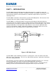
PART 1 - INTRODUCTION The DIT-5200L Non-Contact Displacement Measuring System is an advance in precision measurement technology. It provides exceptional resolution, repeatability, and nulling accuracy for detecting the aligned / centered position of a conductive target relative to a pair of noncontacting sensors. The DIT-5200L is identical in form to Kaman’s previous DIT-5200 product. Enhancements have resulted in lower noise (better resolution) and CE Marking.
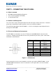
PART 2 – CONNECTING THE DIT-5200L 2.1 What’s Included DIT-5200L Signal Conditioning Electronics 2 or 4 sensors (Typically 15N or 20N) 18” Input/Output Cable 2.2 Cautions and Safeguards The sensor faces may be damaged if allowed to strike the target or other hard surface. Protective plastic caps should remain in place until the sensors are ready for installation. The maximum input voltage to the DIT-5200L is +/-15.5V, exceeding this input voltage will cause damage to the DIT-5200L. 2.
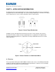
Figure 3 Function Sensor Label Axis 1 Positive Sensor Axis 1 Negative Sensor Axis 2 Positive Sensor Axis 2 Negative Sensor +X -X +Y -Y Sensor Connections The output on the channel will become more positive with movement toward the positive (+) sensor. The output on the channel will become more negative with movement toward the negative (-) sensor. On single channel systems only the Axis 1 (X channel) is used. The system is set up with the sensors as marked.
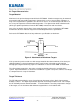
PART 3 – APPLICATION INFORMATION For differential measurement applications, the two electronically matched sensors are positioned on opposite sides or ends of the target. The sensor to target relationship is such that as the target moves away from one sensor, it moves toward the other an equal amount. Figure 4 Sensor/Target Relationship Standard systems come with two measurement axes (four sensors; two per axis) and can therefore be fixtured a number of ways to provided precise x-y alignment.
3.2 Sensor Mounting and Installation The sensors must be securely clamped. A collet type fixture is the best. It is best to clamp the fixture as close to the sensor face as possible (without causing additional loading on the sensor) – this is to minimize expansion differences between the two sensor housings. To insure that the fixturing does not load the sensor and cause performance errors you should have any metal parts approximately 3 sensor diameters away from the tip.
3.4 Optimizing Performance There are several things to be aware of when using the DIT-5200L in order to optimize the performance of the system. Insure that there are no ‘incidental targets’ – i.e. targets that the sensor may see that are not to be measured. Insure that the sensor is not tilted with respect to the target as this will cause additional non-linearity. Make sure that the system is set up with the proper null gap – electrical nulling of the second sensor in a pair is best.
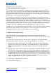
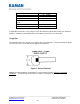
3.6 Target Characteristics Target Material Aluminum is the preferred target material for the DIT-5200L. Aluminum targets may be mounted on materials with more stable temperature characteristics such as Invar or other substrates as long as the target thickness guidelines are observed. Invar is an excellent target substrate as it has a very low expansion coefficient with temperature. The figure below shows aluminum tabs (which give optimal performance from the DIT-5200L) mounted on and Invar fixture.
Material Silver and Copper Gold and Aluminum Beryllium Magnesium, Brass, Bronze, Lead 300 Series Stainless Steel Inconel Thickness, mils (mm) 22 ( 0.56 ) 22 ( 0.56 ) 25 ( 0.64 ) 58 ( 1.5 ) 110 110 ( 2.8 ) ( 2.8 ) In applications where the sensors oppose each other with the target between them, the minimum thickness should be at least double those listed above to prevent sensor interaction Target Size The minimum target size must be 1½ to 2 times the sensor diameter.
PART 4 – CALIBRATION The DIT-5200L systems are shipped from the factory pre-calibrated for a user specified measuring range, sensitivity, and target material. They do not normally require calibration or recalibration. Potentiometer locations for the OEM and enclosure version are the same relative to the sensor and I/O connector positions. The system must be positioned to the null gap by first adjusting one sensor to the null gap and adjusting the opposing sensor for a zero volt output. Reference section 3.
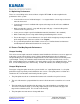
R112 Gain Ch X R117 Offset Ch X R217 Offset Ch Y R212 Gain Ch Y Figure 9 Potentiometer Locations Note: Offset (zero) potentiometers R117 and R217 are not normally installed and are not included in this calibration sequence. 1. Position the target at Null 2. Adjust the offset control for the measuring channel being calibrated to 0+/-0.001V (unless otherwise specified). 3. Position the target at –FS (negative full scale) 4.
PART 5 – GENERAL SPECIFICATIONS & TYPICAL PERFORMANCE Parameter Value Units Comments Target Material Aluminum is preferred Most conductive materials can be considered Null Gap See Data Sheet Range and sensor dependant. See Data Sheet. Range See Data Sheet Output Voltage See Data Sheet +/-10 Volts Typical Non-Linearity <0.5 %FSO Typical Resolution at Null (p-p at 1kHz BW) <0.004 %FSO Typical Resolution at FSO (p-p @ 1kHz BW) <0.015 %FSO Typical TempCo at Null <0.
Sensor/Range Specific Performance Range, Rang Null, Null, 15N 20N Typical Max. Typical +/-mil e mil mm NonNonSensor +/Linearity, Linearity, TempCO mm %FR %FR , %FR/oC 10 10 20 20 35 50 75 0.25 0.25 0.50 0.50 0.90 1.25 1.90 15 20 25 40 40 60 85 0.40 0.50 0.65 1.0 1.0 1.5 2.2 x x x x x x x 0.15% 0.10% 0.25% 0.15% 0.50% 0.25% 0.50% 0.30% 0.20% 0.50% 0.30% 1.00% 0.50% 1.00% 0.02% 0.02% 0.03% 0.02% 0.03% 0.03% 0.
PART 6 - TROUBLESHOOTING 5.1 Insufficient Gain If attempting to recalibrate for a specific sensitivity, measuring range, or for a target different from factory calibration specifications, there may be insufficient gain control to do this. You may need to decrease the desired output in order to calibrate the system. Another cause for insufficient gain could be excessive loading of the sensors by conductive material (other than the target) within the field of the sensors.
APPENDIX A DIT-5200L SENSOR DIMENSIONS 15N Sensor Versions 20N Sensor ______________________________________________________________________________ Kaman Precision Products www.kamansensors.
APPENDIX B DIT-5200L ENCLOSURE DIMENSIONS ______________________________________________________________________________ Kaman Precision Products www.kamansensors.
APPENDIX C TERMINOLOGY Null Gap The point at which a target is equidistant from each sensor of a differential pair. The system output at null = 0VDC. The actual gap is measured from the sensor face to the corresponding target face and includes a required offset (null gap = offset plus maximum measuring range). Offset The minimum distance between the sensor face and the target.