User Manual HIGH TEMPERATURE DISPLACEMENT SYSTEM ******** DO NOT MAKE ANY MODIFICATIONS TO CABLE LENGTH, SENSOR OR CALIBRATED TARGET MATERIALS WITHOUT PRIOR CONSULTATION WITH A KAMAN APPLICATION ENGINEER ******** Copyright © 2000 PART NO: 860064 Rev.
Kaman Instrumentation High Temperature Displacement System User Manual A guide to the use of KDM1925, KDM1950, and KDM1975 displacement measuring systems High Temperature Displacement System
Table of Contents Introduction General Operating Procedures Installation Importance of Oscillator Frequency Synchronization Front Panel Controls The Zero Control The Gain Control The Coarse and Fine Linearity Controls Calibration Procedure Maintenance Troubleshooting Construction and Corrosion Resistance Appendix A -- Sensor Specifications Appendix B -- Electronics Specifications Appendix C -- Sensor Dimensions and Mounting KD-1925 Sensor Dimensions KD-1925 Mounting KD-1950 Sensor Dimensions KD-1950 Mountin
Kaman Instrumentation High Temperature Displacement System User Manual Introduction The Kaman Instrumentation line of High Temperature Displacement Transducers are designed to provide accurate non-contacting measurement of conductive surface motion in hostile environments. Output is directly proportional to displacement yielding a linear transfer function for the specific target used in calibration.
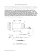
General Operating Procedures Kaman Instrumentation high temperature, noncontacting displacement measuring system is composed of three basic separate components that must be assembled into and operational system. A diagram of the basic set of 8200 electronics required is shown in figure 1. The components of the system are the signal conditioning electronics (items 1,2,3), a low-temperature interconnecting cable (item 4), and sensor (item 5, with integral metal sheathed high temperature cable),.
The electronics type may be either 7200, 8200, or 8200HT type electronics for the KD-1925, but the KD-1950 and KD-1975 systems are only available in the 8200HT version. The main difference is the frequency of operation which may vary depending on the application. The standard operating frequencies are listed in appendix B for each sensor. The output voltages are per the table in appendix A unless otherwise specified.
During factory calibration the grounding was maintained via the electronics only. Further grounding along the cabling or sensor should have minimal effect on the sensitivity since special high temperature cabling was developed to alleviate this effect. Careless handling of the sensor either directly during installation or indirectly during operation may seriously damage the sensitive front portion of the sensor.
High Temperature Displacement System
The sensor were calibrated per the specifications listed in appendix A or as specified in the sales order. The measuring system is somewhat susceptible to metal objects within its environs besides the target being measured. Change in the calibration may result if metal objects are brought to within approximately 1/2 of the sensor diameter from the side of the sensor. Recommended sensor mounting for the three sensors are shown in Appendix C.
Installation Since sensors and signal conditioning electronics are irreversibly paired during calibration such that zero and sensitivity thermal shifts are minimal, it is imperative that this same pairing be maintained during installation and operation. Calibration records include serial numbers for each component of a particular system and installation must be consistent with these numbers for proper operation. The end of the sensor is fragile and if damaged can alter or impair the system performance.
The metal sheathed cables and transducer will withstand a minimum continuous service temperature of 1000oF (See appendix A for exact numbers which depend on the sensor). This sheathed cable is designed to withstand a 6.35mm (.25 inch) minimum bend radius without degradation providing an appropriate mandril is used. The first bend should be as far from the sensor as practical to avoid bends at the cable-sensor weld. The cabling is shipped in a coil approximately 30.5 centimeters (12 inches) in diameter.
Importance of Oscillator Frequency The Oscillator frequency used will vary depending on the sensor and type of target used. The high temperature displacement systems generally operate at a lower frequency than other Kaman transducers. The reason they operate at low frequencies is to allow the transducer to "see through" the protective covering on the sensor (normally Inconel) and to optimize the sensor output from a specific target material.
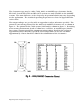
Front Panel Controls The front panel consists of 4 potentiometer adjustments to be used during calibration. The front panels are shown in figure 7 and 8 for reference.
The Zero Control The Zero control allows you to adjust the offset voltage in the system. It is influenced slightly by the gain control -- so if you adjust the gain you will probably need to readjust the zero slightly.
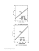
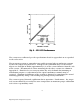
The Gain Control The gain control affects the slope (generally referred to as the sensitivity) of the system output. The effect of this control is depicted in figure 10. The Coarse and Fine Linearity Controls The Coarse and Fine linearity controls affect the linearity of the system output. They are an offset to the system output ahead of the log amplifier.
Calibration Procedure All the sensors were calibrated at Kaman Instrumentation using a flat or curved target either specified or furnished by the customer. The target thickness is a minimum of 12.7 mm (.50 inches). Calibration of the sensors was optimized at 25oC (77oF using the mounting geometry described in appendix C. The following procedure (using suitable micrometers or their equivalent to vary the spacing from the sensor to target) is used for adjustment of the transducer.
Maintenance The sensor is an irreversibly sealed unit and consequently routine maintenance is limited to care and cleaning. The case will appear as oxidized metal due to the operational temperature. The front of the sensor may appear darker than the rest of the case due to the higher temperatures it encountered during fabrication. Any foreign matter other than these oxides should be removed. The following steps should be used as a guide: A.
Troubleshooting Troubleshooting the system is limited primarily to isolating the malfunction between the various components. The sensor can be checked for coil integrity as follows. A. Disconnect the solid sheathed cable from the flexible cable. B. Using and ohm-meter that has a battery voltage of 1.5 volts or less check continuity form each individual pin of the connector to the sheath. These values should be approximately 4.5 ohms at room temperature.
Construction and Corrosion Resistance The exterior of the sensor is fabricated of Inconel Alloy 625*, an alloy that is particularly useful in contact with high temperature steam. Since no dissimilar material joints are exposed to steam, corrosion by galvanic action should be minimal. Cable sheaths are of Inconel Alloy 600. All internal materials and components are sealed from the test environment.
Appendix A -- Sensor Specifications Measuring Range KD1925 .050" (1.27 mm) KD1925M .040" (1 mm) KD1950 .150" (3.81 mm) KD1950M .100" (2.54 mm) KD1975 .200" (5 mm) KD1975M .100" (2.5 mm) Sensitivity 50 mV/mil 50 mV/mil 10 mV/mil 10 mV/mil 10 mV/mil 10 mV/mil Output Voltage 0 - 2.5 Vdc 0 - 2 Vdc 0 - 1.5 Vdc 0 - 1 Vdc 0 - 2 Vdc 0 - 1 Vdc Offset (typical) .005" (.127mm) .002" (.0508mm) .010" (.254mm) .005" (.127mm) .010" (.254mm) .005" (.
Appendix B -- Electronics Specifications KD1925M 7200 or 8200 KD1950 8200HT KD1950M 8200HT KD1975 8200HT KD1975M 8200HT Operating 0 - 50oC Temperature (32 - 122oF) Range (Electronics) 0 - 50oC (32 - 122oF) 0 - 50oC (32 - 122oF) 0 - 50oC (32 - 122oF) 0 - 50oC (32 - 122oF) 0 - 50oC (32 - 122oF) Oscillator Frequency 300 kHz 125 kHz 125 kHz 62.5 kHz 31.25 kHz Frequency 10 kHz Response (3dB point) (frequency response up to .1xosc available upon request) 10 kHz 10 kHz 10 kHz 2.5 kHz 2.
Appendix C -- Sensor Dimensions and Mounting -21- High Temperature Displacement System
-22- High Temperature Displacement System
Customer Service Information Should you have any questions regarding this product, please contact an applications engineer at Kaman Instrumentation Operations 719-635-6979 or fax 719-634-8093. You may also contact us through our web site at: www.kamaninstrumentation.com.