Instruction Manual KD-2300 Noncontacting Displacement Measuring System EC DECLARATION OF CONFORMITY This apparatus, when installed and operated per the manufacturer’s recommendations, conforms with the protection requirements of EC Council Directive 89/336/EEC on the approximation of the laws of the member states relating to Electromagnetic Compatibility, as required by the Technical Construction File Route to Conformity. This certificate has been issued in accordance with the conditions of regulation No.
Contents Introduction 1 Welcome ....................................................................................................................................1 Customer Service Information....................................................................................................2 Warranty 7A...............................................................................................................................3 Cautions and Safeguards ..................................................
Part IV: Calibration 23 Factory Calibration ..................................................................................................................23 Calibration Interval ..................................................................................................................23 Dimensional Standards ............................................................................................................23 Offset .......................................................................
Introduction Welcome Welcome to the Series 2300 by Kaman — a family of precision, noncontact displacement measuring systems designed to solve a wide variety of position measurement problems. Kaman Precision Product’s MULTI-VIT (MULTI-purpose Variable Impedance Transducer) Displacement Measuring System Model KD2300 series is a non-contacting linear proximity measuring system.
Customer Service Information Should you have any questions regarding this product, please contact an applications engineer at Kaman Precision Products | Measuring 719-635-6979 or fax 719-634-8093. You may also contact us through our web site at: www.kamansensors.com.
Kaman Products Standard Limited Warranty Products of Kaman Precision Products are warranted to be free from defects in materials and workmanship when installed and operated in accord with instructions outlined in the instruction manual. Kaman Precision Products's obligation under this warranty shall be limited to repair or replacement (at the discretion of Kaman Precision Products) of the defective goods returned to Kaman's plant within one (1) year from date of shipment.
Cautions and Safeguards ! This information contains important cautions and safeguards associated with the use of your KD-2300 system. Please read the list carefully before working with the system. • To protect against risk of electrical shock, do not place the system module in water. • Do not operate with a damaged power cord. • Do not let power cords or sensor cables touch hot surfaces. • Unplug all power supplies before attempting to make any system modifications.
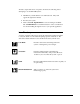
All users, despite their level of expertise, should do the following before attempting to use the KD-2300 system: • • • Familiarize yourself with the icons defined below. They will appear throughout the manual. Inventory the system. Refer to Part III: EQUIPMENT on sensors and targets and Part IV: CALIBRATION for a detailed discussion of the considerations involved in making the right choices for your specific application.
Application Information The system speeds gaging and precision measurements by eliminating errors caused by “feel”. It uses modern electronics (eddy current operating principle) to replace LVDT’s, air gages, capacitance systems, dial indicators, and micrometers. Applications include precision displacement (proximity) measurements of shafts, plates, foils, and other ferrous and non-ferrous metal targets.
Part I: What is the KD-2300? System Technology Kaman Precision Products’s KD-2300 family of displacement measuring systems uses inductive technology to determine the position of a target relative to the system sensor. An AC current flows through the sensor coil, generating an electromagnetic field that radiates out from the sensor. As the conductive target enters this field, the sensor induces a current flow; it produces a secondary opposing field, reducing the intensity of the original.
Nonconductive materials intervening between the sensor and target have little or no effect on system output. Because of this, environmental contaminants, such as oil, dirt, humidity, and magnetic fields, have virtually no effect on system performance. The function of a noncontact displacement measuring system is to monitor the position of a target relative to some reference plane.
Part II: Getting Started Basic System Your KD-2300 system consists of these basic components: • • Sensor(s) Cable(s) Depending upon the system, the standard sensor cable length may be increased in increments of 5 feet (1.55 m) up to a maximum of 30 feet (9.15 m) on special order basis. • • • Oscillator/ Demodulator User manual Accessory kit Module Identification All modules have the following identification: a. Model number b.
Connecting External Power Supply The KD-2300 operates from a ± 15 Vdc power source. If your system was not configured with a power supply, you will need to provide an external power source. The Kaman Model P-34XX power supplies are recommended, although 15 Volt regulated supplies are satisfactory. Use 24 AWG or heavier insulated wires. ! Connecting power to any other than the specified pins may cause damage to the 2300 and / or power source.
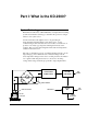
WIRING DIAGRAM USING TWO SEPARATE 15 V LINEAR POWER SUPPLIES 15 V Supply + 15 V Supply - + - user supplied J1 5 1 6 4 2 3 DVM, Recorder, Oscilloscope, or Computer Interface + Output user supplied + - Output - PIN 1 2 3 4 5 6 + 15 Vdc (Positive supply input) Ground (Common supply input) - 15Vdc (Negative supply input) + Output - Output (Common with ground) No connection (Sync output) Figure 1 KD-2300 Instruction Manual Part II: Getting Started • 11
12 • Part II: Getting Started KD-2300 Instruction Manual
Part III: The Equipment Operating Principle* The system uses a principle of impedance variation which is caused by eddy currents induced in a conductive metal target. The coupling between a coil in a sensor and a target is dependent upon their displacement (gap). The electronics consists of an oscillator, linearization network, amplifiers, and a demodulator, which provides an analog voltage directly proportional to displacement.
Accessories Recommended accessories for ease of system calibration and convenience are listed below: • • • • • • • 14 • Part III: The Equipment Power Supply P-3410 provides regulated ± 15Vdc output for 1 measuring system. Input voltage is 105 - 125 VAC @ 50 - 400 Hz. PN Part Number: 852531-001 Power Supply P-3450 provides regulated ± 15 Vdc output for up to 6 measuring systems. Input voltage is 105-125 VAC @ 50-400 Hz.
Sensor Options KD-2300 Instruction Manual Part III: The Equipment • 15
Sensor Specification The table below lists the sensors available for use with the KD-2300 electronics and their standard performance specifications: Sensor Models Measuring Range Typical Offset Linearity Analog Voltage Displacement Sensitivity Thermal Sensitivity Shift * Model Inch (mm) Inch (mm) %FS ** Vdc mV/mil (mm) %FSO/°F .5SU .5SUM 1S 1SM 1SU 1SUM 1U1 2S 2S1 2UB1 3U1 4S1 6C 6U1 8C 10C 10CU 12CU 15U1 30U1 60U1 0.020(0.5) 0.020(0.5) 0.040(1.0) 0.040(1.0) 0.050(1.25) 0.050(1.25) 0.040(1.
Measuring Range The specified linear measuring range for an inductive system is directly proportional to the diameter of that sensor. For any given sensor diameter, unshielded sensors have a greater measuring range than shielded sensors. This is because the sensor’s field will “couple” with the shield, in effect, limiting the amount of field available for interacting with the target.
material (other than the target) that is positioned within 3 times the diameter of the sensor and is a permanent part of the measuring environment. Simulated vs. Application Fixture Install the sensor in the application fixture exactly as it was in the simulated one. When moving from the simulated fixture to the application fixture, deviations may occur through changes in loading or in mechanical position. To ensure maximum accuracy, calibrate the sensor in the actual application fixture whenever possible.
Surface Mounting Surface mounting will not affect a sensor’s calibration assuming there is nothing conductive in the sensor’s “viewing range” other than the target. When surface mounting in a conductive fixture, the sensor face of an unshielded sensor should be 2.5 to 3 times its diameter away from the fixture. The factor for shielded sensors is 0.25 to 0.5 times the diameter. 1.5 TO 2 X * SENSOR DIAMETER SENSOR DIAMETER UNSHIELDED 0.25 TO 0.
Flush Mounting Flush mounting in a conductive fixture requires a cut-out area around the sensor head. The depth and width of the cutout are relative to sensor face diameter as shown in the diagram below. The cutout should never be any smaller than the dimensions arrived at by making these calculations. Smaller width and/or depth can result in loading effects so severe that you may not be able to calibrate the system.
Target Material The essential requirement for a proper target is that it be conductive. In addition, nonmagnetic targets offer greater stability and linearity than magnetic targets (in particular, aluminum, copper and some 300 series stainless steel make ideal targets). Kaman Precision Products can optimize any Series 2300 system to work with either a magnetic or nonmagnetic target. You will find it difficult to use a system tuned for nonmagnetic materials with a magnetic target.
under the face of a sensor. The diagram on the right shows the corresponding analog voltage assuming the rod remains a fixed vertical distance from the sensor. 1 2 3 2 1 3 Target Thickness Nonmagnetic targets with a thickness of 15-20 mils are recommended, and are typically more than adequate for the majority of applications. However, depending on the required accuracy, targets as thin as .5 mil thick have been used.
Part IV: Calibration Factory Calibration All systems are factory calibrated; even so, we recommend that upon receipt you check the calibration and recalibrate the system using one of the procedures outlined on pages of this section. At the factory, systems are calibrated with a typical output sensitivity as shown in Part 3: THE EQUIPMENT, sensor specification table on page 14. We use flat aluminum to optimize for nonmagnetic targets and 4130 cold rolled steel to optimize for magnetic targets.
Offset Offset is the minimum space or gap between the sensor and target. You should position your sensor so that the target never enters this area. When offset has not been considered, linearization of the system can be difficult as the target enters the offset region. The required offset for a given sensor is typically 10 to 20% of its full-scale measuring range. See the Sensor Specifications table in Part 3: EQUIPMENT for sensor offsets.
Calibration Controls You will need to calibrate each measuring channel in your system using the Zero, Gain, and Linearity (Coarse and Fine) potentiometers located on the control end of the module. The controls rotate both clockwise and counterclockwise through the use of a small screwdriver or the supplied calibration tool. A description of each calibration control follows: Clockwise rotation of calibration controls causes the analog output to go more positive; counterclockwise causes more negative output.
Gain Control INCREASED GAIN INITIAL CALIBRATION DECREASED GAIN -OUTPUT +OUTPUT Gain control affects the change in output of a system in volts due to a given change in displacement. In other words, gain controls the sensitivity of the system output. The diagram shows how the slope of the output curve changes as gain is increased and decreased. Linearity Coarse and Fine Linearity controls affect the shape of the system output curve.
VDC Full Scale Calibration offset Bipolar Output Calibration VDC DISPLACEMENT offset High Accuracy Band Calibration VDC DISPLACEMENT offset CALIBRATED RANGE DISPLACEMENT Full Scale Calibration Procedure VDC Full-scale calibration produces an output voltage that varies from 0 Vdc when the target is closest to the sensor (plus offset) to some maximum positive voltage when the target is farthest from the sensor.
1. Install the sensor in the calibration or application fixture, ensuring that when the target is at its closest point to the sensor, there is a gap (offset). With curved targets, decreasing offset will improve linearity; with flat targets, increasing offset slightly will improve linearity. In either case, never allow the target to strike the sensor face. 2. a.
VDC Bipolar Output Calibration offset DISPLACEMENT Use this method when your application is best suited by readouts that represent a positive and negative deviation from some nominal value, in this case, 0 Vdc. Bipolar calibration also provides maximum output sensitivity. (An alternate technique is listed after Steps 1-6 that will provide bipolar output, but not maximum sensitivity).
6. Repeat Steps 3 through 5 as many times as necessary until you reach the desired output voltage at each point. No further adjustment of the Zero, Gain and Linearity controls will be needed when proper calibration is attained. Alternate Bipolar Output Calibration You may not be able to achieve maximum sensitivity using this technique. This method may be preferred if the maximum voltage does not exceed the op-amp saturation voltage (5.5 V for 8 volt internal regulation.) 1.
VDC High Accuracy Band Calibration High Accuracy Band Calibration offset CALIBRATED RANGE 0 DISPLACEMENT This procedure is used to monitor changes in position that are less than the specified linear measuring range of your sensor, or when you are interested in increased accuracy over a smaller range and not concerned about high accuracy outside of that range. The high accuracy band procedure maximizes the linearity of output within a calibrated span.
1. Install the sensor in the calibration or application fixture, ensuring that when the target is at its closest point to the sensor, there is a gap (see the Sensor Specifications table in Part 3: EQUIPMENT , page 14 for offsets). With curved targets, decreasing offset will improve linearity; for flat targets, increasing offset slightly will improve linearity. In either case, never allow the target to strike the sensor face. 2. Define the reduced measurement span you will use. 3.
Appendix A: Glossary Glossary A/D Converter A device that converts an analog voltage to a digital representation. Analog Output Output voltage of a system that is a continuous function of the target position relative to the sensor. Dimensional Standard A standard of measurement or precision reference against which one correlates the output of the system, i.e. a micrometer fixture, feeler gauges, precision ceramic spacers, etc.
Measurement Bandwidth The difference between the upper and lower frequency response limits of a system. KD-2300 system bandwidth is 0 to 50,000 Hz. Noise Any unwanted electrical disturbance or spurious signal that modifies transmitting display or recording of desired data. Offset The required gap between the sensor face and the target at zero range. Usually specified in mils and is dependent upon sensor type.
Appendix B: System Modifications Maximum Sensitivity (Gain Control) When increased sensitivity is needed, rotate the GAIN control clockwise until reaching the desired sensitivity. If the GAIN control reaches the full clockwise position before reaching the desired sensitivity, perform the internal gain modification described below: Remove the cover of the unit by removing the eight cover screws. Using a hobby knife, cut the trace marked “G” (refer to the figure below).
Cut this trace for least sensitive offset (zero) control Cut this trace for maximum sensitivity (gain) G L H PC BOARD Cut this trace for mid sensitive offset (zero) control Synchronization of Multiple Units When two or more sensors are mounted in close proximity, their electronic fields may intermix, causing interference in the form of “beat notes”. (The frequency of the beat notes is the difference between the frequencies of the oscillator demodulator units, usually 10Hz).
E1 & E2 in this area E3, E4, & E5 in this area Lower PC Board FOR SLAVE UNITS ~ Locate the jumpers marked E3, E4, and E5 near the connector end of the PC board. A bold arrow on the silkscreen highlights this area. Solder a jumper wire between E4 and E5. ~ Locate the jumpers marked E1 and E2. Two bold arrows on the silkscreen highlight this area. Using a hobby knife, cut the trace between them. (This removes the crystal from the oscillator circuit).
Appendix C: Troubleshooting Checklist for Basic Troubleshooting This troubleshooting section addresses the problems that commonly arise out of misapplication of the procedures in this manual, simple oversight, or changing environmental conditions. Understanding of the material outlined in this manual and a common-sense approach to system use will preclude most of the problems listed below from happening.
• • • • • Problems with sensor mounting and nonrepeatable fixturing can be sources of trouble: Make sure your calibration fixture is sound and repeatable. When you move the sensor from the calibration fixture to the application fixture, maintain the offset. Make every effort to provide a thermally stable environment to prevent drift. (Kaman can provide temperature compensation, but your best choice is to control the environment if possible).
1.CAUSE: Intermittent cable. This problem is typified by large output changes (full volts vs millivolts) when the cable is moved. SOLUTION: 1. Visually inspect the cable, 2. Test it with an ohmmeter and confirm the variable/short problem while moving the cable, 3. Replace the cable. 2.CAUSE: Open sensor coil, shorted or open cable. A short will yield very low to zero voltage while an open will yield saturation voltage. SOLUTION: 1. Visually inspect, 2.
5.CAUSE: A malfunctioning voltmeter. SOLUTION: Check the system output voltage with a different voltmeter, or inject a know voltage in the voltmeter in use to verify that it is operating properly. 6.CAUSE: Coarse linearity misadjusted. SOLUTION: Recalibrate the system. 7.CAUSE: Beat note interference when using more than one sensor. SOLUTION: Ensure that the sensors are at least 3 diameters apart, or Synchronize your sensor and electronics as described in APPENDIX B. 8.CAUSE: Ground loop.