ThreadChecker Universal TM Noncontact Thread Detection System User’s Manual Copyright © 2008 PART NO: 860510-001A Last Revised: 6/8/11 Kaman Aerospace Corporation Kaman Precision Products Measuring & Memory Systems 217 Smith Street Middletown, CT 06457 www.kamansensors.
This apparatus, when installed and operated per the manufacturer’s recommendations, conforms with the protection requirements of EC Council Directive 89/336/EEC on the approximation of the laws of the member states relating to Electromagnetic Compatibility. Please refer to the Declaration of Conformity or contact Kaman Precision Products for details.
ThreadChecker Universal Kaman’s ThreadChecker Measuring System is a noncontact linear proximity measuring system. This low-cost, easy-to-use system makes precision static and dynamic measurements of the presence or absence of a thread. Features Summary / Advantages • • • • • • • • Easy to Use Universal Electronics for All Sensor Types and Target Types Built in Self Test Small size for efficient system integration: less than 4 cubic inches (80cc) Flexible packaging and performance. Several sensor options.
Electronics The ThreadChecker electronics has one switch and two LEDs visible in the enclosure to provide various setup and status functions. The power led indicates that power is applied and everything is functional if it is green. Red or flashing red on the power LED indicates a problem. The thread or status LED indicates the presence or absence of a thread or teach status (see application information).
Operation of the ThreadChecker Wire colors & pin-out. The wire colors and typical connection diagram are as follows. Teach sequence Before the system is first used it must have the ‘teach’ sequence run. In order to do this you must have a representative threaded and non-threaded hole. The system can be easily calibrated to any new sensor designed for the ThreadChecker as well as for most hole/thread configurations with a simple calibration sequence. 1.
The Switched output This is an opto-coupled solid-state relay. While the switched output can handle a substantial amount of voltage & current (see specifications) it is not infinite. Connect external devices accordingly. There are two modes of operation for the switched output: Window comparator and compatibility/level comparator mode. You can easily switch between the two modes by holding down the button on power up. It will remember the last mode it was set up for the next time you power on.
The LED’s There are two bi-color LED’s on the system. The power LED (labeled PWR) displays whether the system is running or has a fault. The status LED (labeled THREAD) displays the limit output and can flash at different calibration points. The function of the status LED in the Thread Checker is to indicate the state of the switched output. In ‘compatibility’ mode the status LED output mirrors the switch state. When the LED is “off” the switch output is pulled to ground.
Dwell time and Frequency When the sensor is being inserted into a hole there is a certain period of ambiguity at partial insertion. To avoid switching on this ambiguity a form of derivative is used to determine whether the sensor is in motion or is at the measurement point. The system will effectively delay of approximately 10-20 milliseconds after it stops moving before it recognizes the values for the limits (the analog output does not do this and is continuous).
Push Button Switch Operation and User Configuration Switch Operation Holding the button down for longer than one second Holding switch down during power up for less than 10 seconds Holding switch down during power up for more than 10 seconds Holding switch down for longer than 10 seconds (until the status light stops blinking) Result The status light starts blinking. On release it acquires the air readings for all frequencies.
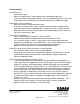
Troubleshooting No LED’s are on. - Check power input - Make sure power input is correct polarity and connected to right wires - If you can verifiy that the proper voltage is across the power input pins +15 to +30V on the brown wire, the blue wire connected to ground, then contact the factory Power LED is red all of the time. - Make sure sensor is connected and is tight - If sensor is connected, do a “teach” function.
Electronics Mounting Instructions Mounting the ThreadChecker electronics module can be done using the two holes in the enclosure, and an M-4 (or 6-32) screw (see below). The DIN mount attachment can also be used to allow mounting on a DIN rail. Positioning the electronics module so that it is not the low point in the cable will keep liquids from running down the cable and into the electronics. Take care to route the sensor cable to avoid crushing or crimping it during use.
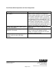
Thread Sensor Specifications: 2 mm Sensor Hole sizes 3mm-5mm, #5-#10 Model/Part # 2mm/855641-303 4 mm, 6 mm, 10 mm Sensors Hole sizes 6mm-7mm, #12-5/16” 8mm-10mm, 3/8”-1/2” 12mm-14mm, 9/16”-3/4” Model/Part # A B 4mm/855641-602 M8x1 4.0 (0.16) 6mm/855641-802 M8x1 5.8 (0.23) 10mm/855641-1202 M12x1 9.5 (0.38) External Thread Sensors Stud sizes Model/Part # 4mm-6mm, #6-#10 6mm/855800-605 8mm-10mm, #12-3/8” 8mm/855800-805 A M18x2.5 M24x3 Copyright © 2008 PART NO: 860510-001A Last Revised: 6/8/11 B 31.
ThreadChecker Specifications ELECTRICAL INPUT Voltage: 15 VDC to 30 VDC (reverse polarity protected) Current: 50 to 100 mA ANALOG OUTPUT Current: (short circuit protected) Impedance: 50 ohms Voltage: 0-10 VDC SWITCHED OUTPUT Opto-Isolated Load Current: 80 mA maximum AC or DC Load Voltage: 30V rms, 42.