9800 0329 01 a GB 840M Date Code 0011L2001
Service and Repair Manual Model 840M 2 General For best performance hammers should be serviced at regular intervals, any indication that the hammer is not performing as specified should be investigated to prevent any adverse damage occuring. ALL SEALS, GASKETS, GREASE OR OTHER PARTS DEEMED NECESSARY FOR SERVICING ARE IN THE SERVICE KIT. ALL NEEDLE ROLLER BEARINGS SHOULD BE PRESSED WITH THE ROUNDED EDGE ENTERING THE BORE FIRST, AND THE PRESS TOOL PRESSING AGAINST THE FLAT SURFACE OF THE BEARING.
Service and Repair Manual Model 840M 00 3 EXAMPLE: 0 Component Parts (Small #) Are Included When Ordering The Assembly (Large #). %SEE PAGE 5 FOR ADDITIONAL LUBRICATION AND SERVICE NOTES FIG. 1 4 8 10 11 12 13 14 15 16 17 22 23 26 27 28 29 30 31 32 33 34 35 37 42 46 47 50 51 52 53 63 66 86 PART NO.
Service and Repair Manual Model 840M 4 Chamfer for barrel washers (119) are to face to the outside, as shown. %SEE PAGE 5 FOR ADDITIONAL LUBRICATION AND SERVICE NOTES NOTE: Do not wash clutch gear assembly (57). If needed, wipe off with a dry rag. Coat gearcase seal (62) with lubrication prior to placement in the gearcase (38). Use Blue Loctite #242 on screws (24), two places.
Service and Repair Manual Model 840M FIG. 2 5 6 7 9 12 18 20 24 25 36 37 38 39 43 44 48 49 54 55 56 57 58 62 64 65 67 68 69 70 71 72 73 74 75 76 80 81 84 85 87 88 89 90 97 98 101 102 103 104 105 106 107 108 109 111 112 113 114 115 118 119 121 124 125 PART NO.
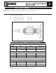
Service and Repair Manual Model 840M 6 Press metal insert of fan to here. 30 30 3 Press fan (3) onto armature (30) such that the metal insert of the fan bottoms against the fan journal shoulder of the armature shaft. After the armature assembly (30) is installed into the tool, the bearing cup (86) is to be placed on the rear armature bearing (1), (already pressed onto the armature shaft), prior to assembling the motor cover (47) to the tool.
Service and Repair Manual Model 840M 7 NOTE: Module wires #3 and #4 are not polarity sensitive. WIRING SPECIFICATIONS TERMINAL DESCRIPCode Wire No. Wire Color Origin or Gauge Length 1 Black Blade Hsg. ----- Component of blade housing assembly. 2 White Blade Hsg. ----- Component of blade housing assembly. 3 Black Elect. Mod. ----- Component of electronics module. Strip 1/4" for T1. 4 Black Elect. Mod. ----- Component of electronics module. Strip 1/4" for T1. Part No. Qnty.
Service and Repair Manual Model 840M ELECTRICAL TESTING Electrical test Before assemby all electrical parts MUST be checked for safety, and that they conform to specification. Testing the Armature (Flash Testing) A Armature shaft to lamination pack 1500 Volts (min) B Lamination pack to commutator 1200 Volts (min) C Armatuure shaft to commutator 3000 Volts (min) ELECTRICAL PERFORMANCE TEST READINGS ARMATURES MODEL 110V 120V 220V-240V 840M .440/.506 Ohms .440/.506 Ohms 1.283/1.
Service and Repair Manual Model 840M 9 WARNING LETHAL VOLTAGES PRESENT!! IMPORTANT On completion of the assembly, the unit must be flash tested at 4000 volts. Flash Test 1. With the breaker completely assembled and with the switch "ON", apply 2000 volts initially and increase rapidly to 4000 volts between the main casting and one of the pins of the plug on the power supply cord. Apply test to both live and neutral pins. 2.
Sickla Industriväg 1A, S-105 23 Nacka Sweden Telephone: +46 (0) 8 743 9600 Fax: +46 (0) 8 743 9650 9800 0329 01 a 54-24-1025 Drwg.