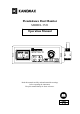
Piezobalance Dust Monitor MODEL 3521 Operation Manual PIEZOBALANCE DUST MONITOR MODEL 3521 Read this manual carefully and understand the warnings before operating the instrument. Keep this manual handy for future reference. 03002 11 .
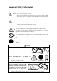
Important Safety Information Types and definitions of warning signs used in this operation manual are shown below. Danger: To prevent serious injury or death. Items under this heading show measures to prevent serious injury or death, which may result if the instructions in this manual are not observed and the instrument is operated inappropriately. Caution: To prevent damage to the product.
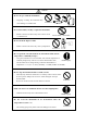
Caution * Do not drop or strike the instrument. …… Dropping or hitting the instrument may cause damage or a malfunction. Prohibition * Never disassemble, modify or repair the instrument. …… Failure to observe the above may cause a short circuit or a malfunction. Do not modify / disassemble * Do not block the impactor inlet. …… Failure to observe the above may cause a pump failure. Prohibition * Do not perform a measurement in an environment with extreme temperature or humidity changes.
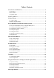
Table of Contents 1. Part Names and Functions ......................................................................................1 1.1 Part Names....................................................................................................................... 1 1.2 LCD Screen ..................................................................................................................... 2 1.3 Operation Keys ........................................................................................
10. Troubleshooting....................................................................................................23 11. Warranty and After-sales Service .......................................................................24 12. Contact Information ............................................................................................
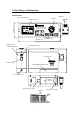
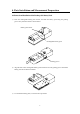
1. Part Names and Functions 1.1 Part Names Impactor (unit: mm (inches)) Needle 65 mm (2.6”) Display screen PIEZOBALANCE DUST MONITOR MODEL3521 180 mm (7.1”) Display screen contrast adjustment Operation keys Cleaning port Power switch Rechargeable battery pack AC adapter socket Cleaning device Battery pack release Sponges 1 Cleaning device lock 150 mm (5.
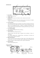
1.2 LCD Screen c b a d a. Date & Time: g f e h Indicates current date & time. b. Sampling Time: Sampling time can be quick set to either 24s, 120s or custom set from 1-60 min. c. Data Record: Indicates the current number of data records (Max.500). When a measurement is complete, “STORE” will flash here. To save the data, press [MEMORY]. d. Measurable Range: The remaining measurable range is indicated by a bar indicator, which moves from left to right as the sensor absorbs dust and the range decreases.
2. Battery Indicator Remaining battery life is displayed when the instrument is powered on. The battery indicator changes as shown below: Full ¾ ¾ Half Requires Battery indicator recharge flashes Automatic power off The battery indicator flashes when the battery voltage drops below 9.3V. The AC/DC adapter must be connected immediately to continue measuring. If the adapter is not connected, the instrument will power off automatically.
3. Battery Charge 3.1 AC/DC Adapter For prolonged measurements, the instrument should be powered using the supplied AC/DC adapter (when AC100-240V power is available). Insert the adapter jack into the adapter socket on the instrument first, and then to a power outlet. Adapter jack Adapter socket Adapter When AC power is supplied, the battery charging status bar will display on the screen. While the battery is being charged, the bar indicator will move.
4. Parts Installation and Measurement Preparation 4.1 Removal and Installation of the Rechargeable Battery Pack 1) Press the rechargeable battery pack release, and slide the battery pack along the guiding groove away from the release as shown below. Battery pack release Rechargeable battery pack Guiding groove 2) Align the tabs on the rechargeable battery pack with the slots in the guiding groove and lift the battery pack free from the instrument.
4.2 Accessing and Storing the Cleaning Device 1) To access the cleaning device, hold the cleaning device while sliding the lock away from the cleaning device as shown below. Cleaning device Cleaning device lock Rechargeable battery pack 2) After the lock is released, remove the cleaning device by lifting the front end.
4.3 Confirming the Sensor Condition When the instrument is powered on, the screen below will display a flashing “WAIT” message in the operating status field. After approx. 10 seconds the sensor will stabilize and the “WAIT” message will stop flashing. The measurable range of the sensor can be confirmed by the bar indicator and the frequency displayed on the screen. 1) Confirming the Measurable Range using the Bar Indicator: The bar indicator will be at full length immediately after cleaning.
4.4 Cleaning the Sponge Preparation Before Cleaning 1) The sponge on the cleaning device must be moistened before use. If the sponge is dirty or stained, put the cleaning device into a vessel filled with clean water and a few drops of neutral detergent, and let it soak for a few minutes (this is not necessary for a new product). 2) When the stain is removed, rinse the sponge under running water making sure to completely remove all the detergent.
4.5 Cleaning the Sensor First, confirm that the high voltage is turned off. Then align the front end of the cleaning device with the cleaning port, and slowly insert the cleaning device with the sponge side facing down. The cleaning device must be inserted up to the scale line indicated on the back side of the cleaning device. When the scale line is flush with the port, stop and wait for approximately 20 seconds. Then, insert the cleaning device further, and pull it out from the other side.
4.6 Adjusting the Impactor Position The impactor may be set at three angles: 0°, 45° and 90°. Turn the impactor to the desired angle. (Note: The instrument has built in stops for each angle.) Rotation angle: 0° Rotation angle: 45° Rotation angle: 90° 4.7 Sampling Time For instructions on how to set the sampling time, see Section 6. Settings Menu. The initial setting of the sampling mode is 120s. Change the setting according to the dust concentration of the environment to be measured.
5. Measurement Method 5.1 High Voltage Supply When the instrument is turned on, the flashing “WAIT” message will be displayed. After a brief delay, the “WAIT” message will stop flashing, and high voltage can be supplied. Press [MEAS/CLN] to supply high voltage. The pointer at the left end of the high-voltage indicator frame will move toward the right. The pointer will stop at the center of the frame under the black block.
5.2 Measurement Start To start a measurement, press [START] after the operating status has changed to “READY”. The “READY” message will change to an elapsed time indicator. During the measurement, the bar indicator will extend as time elapses and the concentration reading will blink. The measurement will stop automatically when the set time has elapsed. The reading will stop flashing and the final concentration value will be displayed.
5.3 Measurement End When a measurement is complete, the concentration reading will stop flashing. The displayed value is the measurement result for the specified sampling time. The operating status display will change from the elapsed time indicator to the “READY” message, and the number of data records will change to a flashing “STORE” message. If you want to save the measurement result, press [MEMORY]. Ignore the message if you do not want to save the result. To start another measurement, press [START].
6. Settings Menu 6.1 Main Menu The following menu will be displayed by pressing [MENU] (when high voltage is not being supplied to the instrument). Use △ and ▽ to select an item. To enter the sub-menu of each item, press [SET]. To return to the measurement screen, select “1. NORMAL” and press [SET]. 6.2 Sampling Time Menu To set the measurement sampling time Select “1” and press SET . Move the cursor to item “2. SAMPLING TIME” of the main menu by using △ and ▽ then press [SET].
6.3 Data Output Menu To select and view stored data Move the cursor to item “3. DATA OUTPUT” on the main menu by using △ and ▽ then press [SET]. The screen shown below will be displayed. If there are no stored data records, the message “There is no record. Please set MENU key” will be displayed. Select a data storage number by using △ and ▽ . When you release the key, the contents of the data record (concentration, date/time, sampling time and sampling status) will be displayed.
it is recommended that you set the time for approx. 30-60 seconds ahead of the actual time, and then confirm the setting by pressing [SET] on “3.SAVE INFO” when the set time matches the actual time. 6.5 Communications Menu To set the communications baud rate Move the cursor to item “7.COMMUNICATION” of the main menu by using and press [SET]. The screen shown below will be displayed. Select “1” by using △ and and △ ▽ , ▽ . (The factory default setting is 9600.) Select “1.
6.6 Data Clear Menu To delete stored measurement data Move the cursor to item “5.DATA CLEAR” on the main menu by using △ and ▽ then press [SET]. The screen shown below will be displayed. If there are no data records, a message “There is no record, Please set MENU key” will be displayed. To select a specific range of data records to be deleted: Select “1” by using △ and ▽ then press [SET]. The cursor will move to the START field as shown in the center screen on the left.
7. Printing 7.1 Connecting the Printer Connect the 3521 to the optional printer using the optional printer cable. (Refer to the operation manual of the printer for details.) Set the communication baud rate to 9600 bps. (The factory default setting is 9600 bps, so it is not necessary to set it unless it has been changed by the user.) Communication cable 3521 Printer 7.2 Print Output Menu Power source To print stored data Move the cursor to “4. Print Output” on the main menu and press [SET].
8. Regular Maintenance and Impactor Nozzle Replacement Regular maintenance is required to ensure the long-term accuracy and performance of the instrument. In order to maintain the initial accuracy, it is recommended that the sensor and impactor plate be cleaned before and after use. If the instrument is used for a long time, or used in a high concentration environment, periodical cleaning of the needle is recommended. 8.1 Impactor Cleaning The impactor knob can be removed by turning it counter-clockwise.
8.2 Removing and Cleaning the Needle When the knob is turned left to the “O” (open) mark, the knob will pop up. Pull out the knob slowly to remove the needle. Be careful not to damage the two O rings attached to the needle. To clean the needle you will need an Ultrasonic Cleaner. Prepare a cleaning solution made up of 1/2 of the provided detergent and 1/2 purified water. The cleaning container should hold enough cleaning solution to cover just the lower portion of the needle.
8.3 Installing the Needle To reinstall the needle, look into the inlet from above and align the high-voltage terminal on the side of the needle with the groove inside the inlet, then slowly twist in the needle. When the needle is fully inserted, lock it in place by turning the knob to the “S” mark until it cannot be turned any further. Turn on the power and press [MEAS/CLN] to confirm that high voltage current is being supplied, and that the pointer stops at the center of the high voltage indicator frame.
9. Main Specifications Product Name Piezobalance Dust Monitor Model 3521 Measuring Object Mass concentration of suspended particulate matter in indoor or outdoor air. Operating Temperature Range -10°C to 40°C (14°F to 104°F) Storage Temperature Range -30°C to 60°C (-22°F to 140°F) Measuring Range 0.
10. Troubleshooting Please review the following troubleshooting tips before requesting a repair. Symptom Possible Cause Solution Turn OFF the power and charge the The display does not appear Battery completely discharged. battery. when the power is turned Contact failure of the battery Remove and reinstall the battery on. pack. pack. Adjust the contrast level, located on The contrast of the display is the side of the instrument, with a not adjusted properly. screw driver. Blurred screen.
11. Warranty and After-sales Service KANOMAX Limited Warranty The limited warranty set below is given by KANOMAX with respect to the KANOMAX brand Piezobalance Dust Monitor (Model 3521) and its attachment parts including accessories (hereafter referred to as “PRODUCT”) that you have purchased. PRODUCT you have purchased shall be the only one that the limited warranty stated herein applies to.
KANOMAX. THIS LIMITED WARRANTY SHALL NOT EXTEND TO ANYONE OTHER THAN THE ORIGINAL PURCHASER OF THE PRODUCT, OR THE PERSON FOR WHOM IT WAS PURCHASED AS A GIFT, AND STATES THE PURCHASER'S EXCLUSIVE REMEDY. After-sales Service If the PRODUCT is malfunctioning, please check with “Troubleshooting” to find possible causes first. Repair parts are retained for a minimum period of five (5) years after production cessation of the PRODUCT.
12. Contact Information JAPAN & ASIA KANOMAX JAPAN, INC. 2-1 Shimizu Suita City, Osaka 565-0805, Japan TEL: 81-6-6877-0183 FAX: 81-6-6879-5570 URL: http://www.kanomax.co.jp/ E-Mail: sales@kanomax.co.jp USA & EUROPE KANOMAX USA, INC. PO Box 372, 219 Route 206, Andover, NJ 07821 U.S.A. TEL: (800)-247-8887 / (973)-786-6386 FAX: (973)-786-7586 URL: http://www.kanomax-usa.com/ E-Mail: info@kanomax-usa.com CHINA Shenyang Kano Scientific Instrument Co., Ltd No.