Handheld Laser Particle Counter Model 3886 GEO –α Operation Manual Please read this manual carefully and understand the warnings described in this manual before operation. Kanomax Japan Inc. . Please keep this manual handy for future reference. 02001 06.
Thank you for purchasing a product of Kanomax, Inc. Please read this operation manual carefully and operate the instrument properly by following the instructions given in this manual.
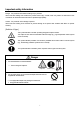
Important safety Information Danger: For prevention of accidents resulting in injury or death Items under this heading show measures to prevent serious injury or death, which may result if the instructions in this manual are not observed and the instrument is operated inappropriately. Caution: For prevention of the damage of product Items under this heading show measures to prevent damage to the product and conditions that affect our product warranty.
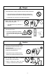
Danger ○ Never disassemble, modify or repair the instrument and its accessories. … This instrument uses a Class 3B laser diode as the light source. Exposure to the laser may cause loss of eyesight and other injury. … Disassembly may cause short circuit and/or other failure. ○ Never bring the probe close to a flammable gas atmosphere. … The heated sensor may cause fire or explosion. Do not use near Flammable gas ○ Never touch the sensor … The sensor is heated during operation.
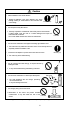
Caution + ○ Set the batteries in the correct direction … Setting the batteries in the wrong direction may cause leakage, leading to contamination of the instrument and Insert correctly surroundings. − ○ Do not wipe the body with solvent … The body may deform or deteriorate. Use soft dry cloth to remove stains. If stains persist, soak the cloth in a neutral detergent and wipe the instrument with a soft cloth. Do not use volatile solvents such as thinner and benzine.
SAFTY OF LASER PRODUCTS Model 3886 GEO-α is Class 1 LASER PRODUCT. CLASS 1 LASER PRODUCT INVISIBLE LASER RADIATION WHEN OPEN DO NOT STRATE INTO BEAM OR VIEW DIRECTLY WITH OPTICAL INSTRUMENTS This instrument is classified into the class 1 laser product as defined by safety of the laser product JIS C 6802(IEC 60825-1). Never, decompose this instrument to preventive exposed you to the laser radiation.
Table of Contents 1. Check of Components.................................................................................................................... 1 1.1 Standard accessories.................................................................................................................................... 1 1.2 Options............................................................................................................................................................ 1 2.
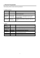
1. Check of Components When unpacking, check the contents in the box using the list below 1.1 Standard accessories Name Model No. Functions Filter Model 3886-03 Used to clean the air flow route inside the instrument with clean air. AC Adapter Model 3886-01 Used for AC powered operation. To be used especially for continuous measurements. Ni-MH (Nickel Metal Hydride) Batteries FNH HR AA 4BF (Fuji Film Battery) Used for battery powered operation.
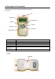
2. Description of Components Name and functions of each component are explained in this chapter. 2.1 Front Inlet Graphic LCD START/STOP Key SET Key △(Up) Key PREV Key ▽(Down) Key POWER Switch Name of component Inlet Graphic LCD SET Key PREV Key POWER Switch △(Up) Key ▽(Down) Key START/STOP Key Functions Inlet for sampling air. Displays measured data and status of operation. To execute a specified item. To return to the previous screen To turn on/off the power To set parameters and values.
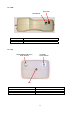
2.3 Side Power Inlet Modular Port Component Modular Port Power Inlet Functions Communication port to transfer data to a printer or PC. Connection for the AC adapter. 2.4 Top Temperature/Humidity (T/H) Probe Terminal Air Velocity Probe Terminal Inlet Component Inlet Temperature/Humidity (T/H) Probe Terminal Air Velocity Probe Terminal Functions Inlet for sampling air. Connection for Temperature/Humidity probe. Connection for air velocity probe.
3. Handling & Cautions 3.1 Power supply Please use the supplied AC adapter and refrain from the battery operation for the long consecutive measurements (more than 2 hours) This instrument has the monitoring function of operating voltage, and battery alarm will be indicated when the voltage goes down below the specified value. If you leave the instrument in such a conditions for a few minutes, the power automatically goes off. In some of measuring mode, the data of measurement in process will not be stored.
3.2 Turning the power on (1) Make sure to remove the cap of air inlet at the top of the instrument. (2) Push POWER switch in the function key. Initial display shows the mode and setup data of previous measurement in WAIT status (Set at SINGLE mode at the time of delivery). Please refer to Chapter 4 for the customizing of measuring mode or method. (3) WAIT sign will change to READY after 10 seconds. Then, measurement can be started by pushing the START key.
3.3 Cautions before starting the measurements 3.3.1 Location This product is designed and produced for the operations in clean room environment. Please refrain from using in the dressing room of clean suits, or in the ordinary environment (e.g. offices, turnery, outdoors, smoking rooms etc.) It will contaminate the internal components and increase the maintenance frequency. 3.3.2 Connection of sampling tube Connect the sampling tube to air inlet for the collection of the air at distant place.
3.4 After the measurement [Cleaning of internals] Internals of the instrument may be contaminated after measurement. Please carry out the following cleaning procedure after finishing the measurement. −The method of cleaning and storage− ① Stop the measurement before cleaning ② Connect the filter to the air inlet at the top of the instrument, using the supplied tube. * There is a possibility that the tube will be folded and inlet will be blocked when connecting the tube to the inlet.
3.5 Measurements using optional probes (Temperature & Humidity, Air velocity) Wind direction mark ◆Air velocity probe * When measuring, set wind direction mark against the wind direction. * Check the tip of probe periodically to confirm that it is kept clean. Dust attached to the sensor will affect the accuracy of the measurement. Wind ―Cleaning of the air velocity probe― ◇ Rinse tip of probe in alcohol if sensor is oily, dry it in low wind.
4. Setting before Measurement 4.1 Selection of measuring mode Power on PREV (1) Push POWER key to input the power supply. Then PREV key. SINGLE 0.3/0.5µm STR:N BEEP:N PR:N SAMPLE 01:00 NO PREV (2) Push PREV key again to proceed to the setup screen 1.REPEAT 4.CALC 2.SINGLE 5.REMOTE 3.CONT (3) Use △ △▽ ▽ key to move the cursor, and push SET key to select the mode you need. SET PREV [1.REPEAT] [2.SINGLE] REPEAT 0.3/0.5µm STR:N BEEP:N PR:N SAMPLE 01:00 2TIMES INT 00:05:00 NO [3.
Measuring mode Content of measurement SAMPLE TIME INT (Time Setting) (Frequency Setting) (Interval Setting) Repeat [5.2] Measurement repeatedly ○ ○ ○ Single [5.3] Measurement once ○ Once ○ Continuous [5.4] Continuous measurement;The measurement ends if STOP is pushed. It measures repeatedly, and mean value, a standard deviation, the maximum value are calculated from data. Only result is done and the store is not done in the data store as for the store doing and each measurement result.
4.2 Setting the measuring condition In the case of REPEAT mode (other mode even same) 1.REPEAT 4.CALC 2.SINGLE 5.REMOTE 3.CONT Use the △ ▽ key to move the cursor, and push the SET key to select the mode you require. △▽ PREV SET ④Warning beep sound ① Measuring mode REPEAT 0.3/0.
SET (2) Push SET key to the item you need to change. REPEAT 0.3/0.5µm STR:N BEEP:N PR:N SAMPLE 01:00 2TIMES INT 00:05:00 NO △▽ (3) Use △ ▽ key to change the setting condition. REPEAT 0.3/0.5µm STR:N BEEP:Y PR:N SAMPLE 01:00 2TIMES INT 00:05:00 NO SET REPEAT 0.3/0.5µm STR:N BEEP:Y PR:N SAMPLE 01:00 2TIMES INT 00:05:00 NO (4) If you finished your set up , push SET key to move the cursor to the position of NO . . △▽ REPEAT 0.3/0.
4.3 Setting of Alarm level 1.REPEAT 4.CALC 2.SINGLE 5.REMOTE 3.CONT PREV MODE
4.4 Selection of option and units
5. Measurement Method 5.1 Explanation of measurement screen ③ Warning beep sound ⑤ Error message ②Number of data records ④Data printing ⑥ Current time ① Measuring mode ⑧Status of measurement ⑨ Sampling number ⑭ Temperature data REPEAT 003BPM 15:25□ WAIT 0.3 0.00E+0/cf 01/06 0.5 0.00E+0/cf 25.5℃ 56.0% 0.
5.2 REPEAT Mode By setting the sampling time, frequency and interval of each measurement, this unit automatically measures as specified and stops after measurements. Interval is the time between the beginning of first measurement and the next. The setting of the particle size (um), data storage (STR), alarm (BEEP) and printout (PR) are possible. Display screen 1. REPEAT 4.CALC 2. SINGLE 5.REMOTE 3. CONT REPEAT 0.3/0.
5.3 SINGLE Mode By setting the sampling time, this unit automatically stops after the specified time. The setting of the particle size (um), data storage (STR), alarm (BEEP) and printout (PR) are possible. Display screen 1. REPEAT 4.CALC 2. SINGLE 5.REMOTE 3. CONT SINGLE 0.3/0.5µm STR:Y BEEP:N PR:N SAMPLE 10:00 OK SINGLE 003BPM 15:25 WAIT 0.3 0.00E+0/cf 0.5 0.00E+0/cf Operation key △ △ Operation explanation POWER Push POWER key to input the power supply.
5.4 CONTINUOUS Mode It is a mode not to set the sample time, and nor to begin, and to end the measurement with the START/STOP key. Particle size(µm)、data store(STR)、Warning(BEEP)、Printer(PR) can be set. Operation key Display screen 1. REPEAT 4.CALC 2. SINGLE 5.REMOTE 3. CONT CONT STR:Y 0.3/0.5µm BEEP:N PR:N POWER Push POWER key to input the power supply. PREV Push PREV key twice to proceed MODE screen △ △ ▽ set Select 3.
5.5 CALCULATION Mode It is a mode by which measures repeatedly, and mean value from the measurement data, a standard deviation, the maximum value, and minimum value are calculated. Only result is preserved, and each measurement result is not preserved in the data store. The measurement frequency can be set at the grain size, the data store, warning, the printer, and the sample time. Display screen 1. REPEAT 4.CALC 2. SINGLE 5.REMOTE 3. CONT CALC 0.3/0.
5.6 REMOTE Mode From computer to measurement mode by remote control (The application software of the option is necessary.) The connection method with the computer is the same method as forwarding the record data. (Refer to 6.3) Display screen Operation key 1.REPEAT 4.CALC 2.SING 5.REMOTE 3.CONT POWER Push POWER key to input the power supply. PREV Push PREV key twice to proceed MODE screen △ REMOTE 0.3/0.5µm BEEP:N Operation explanation △ ▽ ▽ SET Select 5.
6. Data Processing 6.1 Request for stored data in built-in memory… <4.DATA> STORE □□□ 1.DISPLAY 3.PRINT 2.DUMP 4.CLEAR Maximum 500 data can be stored, but the one measurement of CALC mode is regarded as 4 data. For example, if the first data is stored at number 016, next one is stored at number 020.
6.3 Dump of stored data… <4.DATA>→<2.DUMP> Modular jack STORE 139 1. START 001 2. END 139 Start transmitting Put the optional RS-232C cable into the modular jack of GEO-α, and connect the other end of the cable with the PC to transfer the stored data. Do the communication setting of the PC and make the condition that the PC can readout the data.
◆Forwarding data format (1) Repeat, Single, Continuous mode Format 999 crlf 9 crlf 99,99,99 crlf 99,99,99 crlf 99,99,99 crlf xxx crlf x crlf xxx crlf x,x,x crlf Byte 5 3 10 10 10 5 4 5 7 Explanation Store No Measurement mode (1:Repeat、2:Single、3:Continuous) Measurement start date Measurement start time Sampling time(hours, minutes, seconds) Particle unit ( CNT , /cf , /m3 ) Temperature unit ( C , F ) Air velocity unit ( m/s , FPM ) Error message (L:Light source, F:Flow rate, O:Over the maximum concentrati
(2) Calculation mode Format 999 crlf 9 crlf 99,99,99 crlf 99,99,99 crlf 99999 crlf 99,99,99 crlf xxx crlf x crlf xxx crlf x,x,x crlf 9.999E+99, 9.999E+99, 999999999, 999999999 crlf 9.999E+99, 9.999E+99, 999999999, 999999999 crlf 9.999E+99, 9.999E+99, 999999999, 999999999 crlf 9.999E+99, 9.999E+99, 999999999, 999999999 crlf 9.999E+99, 9.999E+99, 999999999, 999999999 crlf 999.9, 999.9, 999.9, 999.9 crlf 999.9, 999.9, 999.9, 999.9 crlf 9.999, 9.999, 9.999, 9.
6.4 Printout of stored data… <4.DATA>→<3.PRINT> Modular jack Put the optional Printer cable into the modular jack of GEO--α, and connect other side of the cable with the Printer to print the stored data. STORE 139 1. START 001 2.
◆ Example of printout (1) Repeat, Single, Continuous mode 2000/03/21 16:40:00 REPEAT (3) During measurement (Repeat, Single, Continuous mode) E= STORE 10 05:30 0.3um 564700 CNT 0.5um 10457 CNT 1.0um 323 CNT 3.0um 36 CNT 5.0um 8 CNT 23.2℃ 45.7%RH 2000/03/21 16:40:00 E=LFO REPEAT 05:30 1 0.3um 564700 CNT 0.5um 23.2℃ 10457 CNT 45.7%RH 0.64m/S Only two particle sizes are printed.
(2) Calculation mode (4) During measurement(Calculation mode) 2000/03/21 16:40:00 E=LFO 2000/03/21 16:40:00 CALCULATION CALCULATION STORE 13 05:30 E= 05:30 10TIMES 10TIMES 0.3um AVE 6.66E+04 CNT 0.3um AVE 6.66E+04 CNT STD 3.94E+03 CNT STD 3.94E+03 CNT MAX 71334 CNT MAX 71334 CNT MIN 60875 CNT MIN 60875 CNT 0.5um AVE 2.78E+03 CNT 0.5um AVE 2.78E+03 CNT STD 2.76E+02 CNT STD 2.76E+02 CNT MAX 3096 CNT MAX 3096 CNT MIN 2422 CNT MIN 2422 CNT 1.0um AVE 9.83E+01 CNT STD 3.
6.5 Deletion of stored data… <4.DATA>→<4. CLEAR > STORE 139 CLEAR YES ALL the stored data will be deleted by executing this function.
7. How to Use Option Probes 7.1 Option probes Temperature/Humidity probe Model 0842 Air velocity probe Model 0843 7.2 Installation of probes The T/H probe and Air Velocity probe must be inserted into “T/H” (refer to 2.4) and “VEL”, respectively, and the lock screw cap must be provided. Make sure to turn OFF the instrument before inserting and removing the probe.
7.3 Setting of display To provide the installation and display setting of each probe, please refer to 4.4. To set the alarm, please refer to 4.3. 7.4 Extension rod for air velocity probe When you want to measure the air velocity right under the filter which is located at a high position, extension rod Model 0843-01 (optional) can be used. Insert the probe into the rod from the side of the sensor. When inserting, please pay close attention not to touch the velocity sensor.
8. Error Message Error display location (L, F, O) Error display location (M) REPEAT 003BPM 15:25 L WAIT 0.3 0.00E+0/cf 01/06 0.5 0.00E+0/cf 25.5℃ 56.0% 0.25m/s Error message Content of error L Laser Error F Flow Error O Maximum Concentration Exceeded M Printer Buffer Exceeded The error message will be displayed at the right of the time display as shown left. The initial letter of each error will be displayed according to the priority order of errors.
9. Battery Check BATTERY REPEAT 003BPM 15:25 WAIT 0.3 0.00E+0/cf 01/06 0.5 0.00E+0/cf 25.5℃ 56.0% 0.25m/s (1)First Alarm When the battery voltage becomes less than 4.5 V, the message "BATTERY" will be indicated at the top of the display (First Alarm). In approx. 5 minutes after the First Alarm, the display will switch to the following screen (Second Alarm). When the Second Alarm is given, the pump, laser radiation and software will stop, and the POWER key will become ineffective.
10. Specification Measuring particle size Light Source Counting Efficiency Zero Count Coincidence Loss Flow Rate Sampling Time Sampling Frequency Mode of measurement Display Error sign Interface Communication protocol Buffer Memory Power supply Operating hours Dimensions Weight Environment operation condition Standard Accessories Options Temperature/Humidity Probe 0.3, 0.5, 1.0, 3.0, 5.0µm Laser Diode Meets JIS B9921 Meets JIS B9921 Less than 5% at 2,000,000 particles/cf 0.1 cfm (2.
11. Troubleshooting Symptom Possible Cause / Corrective Action AC adapter is not inserted properly. → Confirm the AC adapter The display does not appear even Batteries level is low or empty when the power is turned ON. → Replace the batteries, or → Charge the batteries (Ni-MH) Measurement time with the Ni-MH Charging is insufficient → Charge the batteries battery is short. Battery deterioration → Replace with new Ni-MH batteries Displayed reading blinks.
12. Warranty and After Service Warranty ¾ A warranty card is not included in this product. ¾ The instrument (excluding consumables such as batteries) is warranted against defects in materials and workmanship under normal use for a period of one year from the date of original purchase. After Service ¾ When you have a problem with your unit, please check out the “Troubleshooting” section first.
13. Contact Information U.S.A. KANOMAX USA, INC. PO Box 372, 219 Route 206, Andover, NJ 07821 U.S.A. Tel: (800)-247-8887 / (973)-786-6386 FAX: (973)-786-7586 URL: http://www.kanomax-usa.com/ E-Mail: info@kanomax-usa.com JAPAN KANOMAX JAPAN, INC. 2-1 Shimizu Suita City, Osaka 565-0805, Japan TEL: 81-6-6877-0183 FAX: 81-6-6879-2080 URL: http://www.kanomax.co.jp/ E-Mail: sales@kanomax.co.jp CHINA Shenyang Kano Scientific Instrument Co., Ltd No.