Handheld Laser Particle Counter MODEL 3887 Operation Manual Read this manual carefully and understand the warnings described in this manual before operating the product. Keep this manual handy for future reference. 06001 07.
Thank you for purchasing a product of Kanomax, Inc. Please read this operation manual carefully and operate the instrument appropriately by following the instructions given in this manual.
Important Safety Information Types and definitions of warning signs used in this operation manual are shown below. Danger: To prevent serious injury or death Warnings in this classification indicate danger that may result in serious injury or death if not observed. Caution: To prevent damage to the product. Warnings in this classification indicate risks of damage to the product and performance failure that affect the product warranty if not observed.
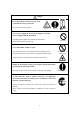
Danger ○ Never disassemble or heat the battery pack, or discard the battery pack in fire. - The battery pack may explode. Explosive Handle Properly ○ For AC power supply, do not use the AC adapter other than the one supplied with the instrument. - An inappropriate adapter may damage the instrument. - It may generate heat and cause fire. Prohibition ○ Never disassemble, modify or repair. - This instrument uses a Class 3B laser diode as the light source.
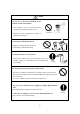
Caution ○ Do not use or keep the instrument in hot, humid, or dusty environment. - The instrument may not function properly outside the specified temperature range. Prohibited Installation - Exposure to direct sunlight may discolor or deform the instrument. ○ Do not drop or hit the instrument. - Dropping or hitting the instrument may cause damage and malfunctioning. Prohibition + ○ Set batteries in the correct direction.
Caution ○ Pull out the plug when the instrument is not in use. - Failure to observe the above may cause electrical shock, fire hazard, and circuit damage. ○ If the instrument is not to be used for a long period, the batteries must be removed from the battery compartment. Do not leave spent batteries in the battery compartment. - Failure to observe the above may cause battery leakage.
Table of Contents 1. Packing List ............................................................................................... 1 1.1 Standard Accessories ........................................................................................................... 1 1.2 Optional Accessories (Sold Separately) .............................................................................. 1 2. Description of Components....................................................................... 2 3.
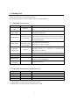
1. Packing List Check all components when opening the package. For purchasing optional accessories, please contact your local distributor. 1.1 Standard Accessories Item Filter, Tube AC Adaptor, Power Cable Ni-MH Batteries Rapid Charger Application Software CD Model 3887-03*1) 3887-01*2) HR-3U (or product of same specification) NC-NQR02 (or product of same specification) S388-70 Description To clean the air flow path inside the instrument with clean air.
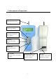
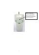
2. Description of Components Inlet 2.83L/min suction volume START/STOP Key To start/stop sampling ENTER Key To execute a menu and enter a setting PREV Key To switch the display screen POWER Key To turn ON/OFF the power. ▲ ▼ Keys To select a menu and change a setting. Communication Port DC Jack To communicate with a computer or printer. To supply power with a dedicated AC adapter.
Battery Compartment Use four (4) AA rechargeable batteries or alkaline batteries. Operating hours by battery power are only ensured when using the supplied Ni-MH batteries.
3. Precautions for Use The following precautions must be taken when using the instrument. ● Sampling There are possibilities of particle deposit/rescattering when sampling is performed by using a tube connected to the inlet. It is recommended that sampling is performed without using the tube. However, if a tube is required for sampling, the tube recommend below must be used. ● Sampling Tube Recommended Sampling Tube: TYGON Inner Diameter 4.3mm × Outer Diameter 7.
4. Measurement Modes The instrument is equipped with six (6) measurement modes. ● REPEAT Mode (Suitable for repeated measurement at a same location.) Measurement of a certain sampling period and interval can be repeated from twice to infinite number of times. When storing the measurement data, the maximum number of measurements is 10,000 times. ● SINGLE Mode (Single measurement which stops when set sampling time has elapsed.) Measurement stops automatically when set sampling time has elapsed.
4-1 REPEAT Mode Setup procedure is shown below. (Character positions may not correspond to the actual screen.) Power Up Measurement Setting Screen
REPEAT 30B 20:32 READY 0.3 0.00E+0/m3 0.5 0.00E+0/m3 00/02 5.0 0.00E+0/m3 Press START/STOP key REPEAT 30B 20:32 RUN 0.3 0.00E+0/m3 00:59 0.5 0.00E+0/m3 01/02 5.0 0.00E+0/m3 The measurement unit can be changed by using the ▲▼ key. CNT : Integrated value /m3 : Number of particles per one cubic meter. /cf : Number of particles per 28.3L. WAIT… 30B 20:32 0.3 0.00E+0/m3 20:42 0.5 0.00E+0/m3 01/02 5.0 0.00E+0/m3 [Display of Optional Specification] REPEAT 30B 20:32 WAIT 0.3 0.00E+0/m3 0.5 0.00E+0/m3 00/02 1.
Cursor Operation The cursor moves each time the “ENTER” key is pressed. LOC.021→LOC.021→LOC.021→STR:N→BEEP:N→ Switch between Y/N by using the ▲▼ key. Change between 0-9 by using the ▲▼ key. SAMPLE 01:00→SAMPLE 01:00→SAMPLE 01:00→SAMPLE 01:00→ Change between 0-9 by using the ▲▼ key. 2TIMES→ 2TIMES→ Change between 0-9 by using the ▲▼ key. Change between 0-9 and to “CONT” by using ▲▼ key. INT 00:10:00 →INT 00:10:00 →INT 00:10:00 →INT 00:10:00→ Change between 0-9 by using the ▲▼ key.
Relation between SAMPL and INT For example, when a measurement is performed with the following setting: REPEAT 0.3/0.5/5.0um LOC.021 STR:N BEEP:N SAMPLE 01:00 2TIMES INT 00:10:00 NO と設定して Press START/STOP WAIT: approx. 10sec Sampling for 1min Suspension Time INT includes Sampling time and Sampling suspension time. 9 Sampling for 1min Measurement stops and measured value will be displayed.
4-2 SINGLE Mode Setup procedure is shown below. (Character positions may not correspond to the actual screen.) Power UP
Press START/STOP key SINGLE 30B 20:32 RUN 0.3 0.00E+0/m3 00:59 0.5 0.00E+0/m3 01/01 5.0 0.00E+0/m3 SINGLE 30B 20:32 END 0.3 0.00E+0/m3 0.5 0.00E+0/m3 01/01 5.0 0.00E+0/m3 Cursor Operation The cursor moves each time the “ENTER” key is pressed. LOC.021→LOC.021→LOC.021→STR:N→BEEP:N→ Switch between Y/N by using the ▲▼ key. Change between 0-9 by using the ▲▼ key. SAMPLE 01:00→SAMPLE 01:00→SAMPLE 01:00→SAMPLE 01:00→ Change between 0-9 by using the ▲▼ key.
4-3 CONT Mode Setup procedure is shown below. (Character positions may not correspond to the actual screen.) Power Up
Press START/STOP key CONT RUN 00:01 30B 20:32 0.3 0.00E+0/m3 0.5 0.00E+0/m3 5.0 0.00E+0/M3 Press START/STOP key CONT STOP 30B 20:32 0.3 0.00E+0/m3 0.5 0.00E+0/m3 5.0 0.
4-4 CALC Mode Setup procedure is shown below. (Character positions may not correspond to the actual screen.) Power UP
Press START/STOP key CALC RUN 09:59 01/10 30B 20:32 0.3 0.00E+0/m3 0.5 0.00E+0/m3 5.0 0.00E+0/M3 Displayed particle size can be changed by using the ▲▼ key. When “STR” is set to “Y”, the data will be stored in the instrument. CALC AVG 0.3um STD 10T MAX MIN 1.23E+4/m3 2.41E+2/m3 5.22E+5/m3 0.00E+0/m3 CALC AVG 1.15E+3/m3 0.5um STD 1.84E+2/m3 10T MAX 5.22E+3/m3 MIN 0.00 E+0/m3 CALC AVG 1.00E+1/m3 5.0um STD 1.00E+0/m3 10T MAX 5.22E+3/m3 MIN 0.
4-5 REMOTE Mode Setup procedure is shown below. (Character positions may not correspond to the actual screen.) Power Up
Press START/STOP key CALC RUN 09:59 01/10 30B 20:32 0.3 0.00E+0/m3 0.5 0.00E+0/m3 5.0 0.00E+0/M3 Displayed particle size can be changed by using the ▲▼ key. When “STR” is set to “Y”, the data will be stored in the instrument. CALC AVG 0.3um STD 10T MAX MIN 1.23E+4/m3 2.41E+2/m3 5.22E+5/m3 0.00E+0/m3 CALC AVG 1.15E+3/m3 0.5um STD 1.84E+2/m3 10T MAX 5.22E+3/m3 MIN 0.00 E+0/m3 CALC AVG 1.00E+1/m3 5.0um STD 1.00E+0/m3 10T MAX 5.22E+3/m3 MIN 0.
4-6 ISO>4 Mode Setup procedure is shown below. (Character positions may not correspond to the actual screen.) Power Up Measurement Setting Screen LOC.: LOC number can be used for identifying room numbers or measurements. Setting of this item is not mandatory. STR: Used when storing data in the instrument. When storing the data, select “Y” by using the ▲▼ key. Select “N” if you do not want to store the data. BEEP: Alarm goes off when alarm level is exceeded. SAMPLE: Sets sampling time.
ISO>4 30B 20:32 READY 0.5 0.00E+0/m3 5.0 0.00E+0/m3 00/02 1POINT Press START/STOP key ISO>4 RUN 00:59 01/02 ISO>4 END 02/02 ISO>4 WAIT 02/02 30B 20:32 0.5 0.00E+0/m3 5.0 0.00E+0/m3 1POINT The measurement unit can be changed by using the ▲▼ key. CNT : Integrated value /m3 : Number of particles per one cubic meter. /cf : Number of particles per 28.3L. 30B 20:32 0.5 0.00E+0/m3 5.0 0.00E+0/m3 NEXT POINT? 30B 20:32 0.5 0.00E+0/m3 5.0 0.00E+0/m3 2POINT ISO>4 30B 20:32 READY 0.5 0.00E+0/m3 5.0 0.
ISO>4 END 02/02 30B 20:32 0.5 0.00E+0/m3 5.0 0.00E+0/m3 FINISH? ISO>4 END Operate by using ▲▼ key Press ENTER key ISO>4 END 02/02 ISO>4 END 02/02 UCL 0.5um UCL 5.0um 30B 20:32 0.5 0.00E+0/m3 5.0 0.00E+0/m3 CALCULATE? 30B 20:32 0.5 0.00E+0/m3 5.0 0.00E+0/m3 EDIT TIMES? 2POINT AVG 6.75E+2/m3 STD 0.10E+0/m3 UCL 9.99E+2/m3 2POINT AVG 0.02E+1/m3 STD 0.0.0E+0/m3 UCL 0.01E+1/m3 20 02/02 30B 20:32 0.5 0.00E+0/m3 5.0 0.
5. View Stored Data Data stored in the LPC can be viewed on the screen or by printing. Displaying on the LPC screen --------------------Printing output --------------------------------------- 21 View in “DISPLAY” mode. An optional printer and printer cable sold separately are required for printing.
5-1 Viewing Stored Data on LPC Screen The data stored in the LPC can be viewed on its screen by the following procedure. Power Up
5-2 Printing Stored Data Required Items: To print the measured data, a dedicated cable and printer is required. Printer Cable Printer MODEL 3887-07 DPU-H245 Connect the printer cable to the communication connector of the instrument. Power up the printer. (Internal setting is not necessary.) The data stored in the instrument can be printed out from the dedicated printer connected to the instrument by the following procedure. Power Up
● Print Example (1) REPEAT, SINGLE, CONTINUOUS Mode 2000 / 03 / 21 REPEAT 16:40 E= RECORDS : 00008 LOCATION : 188 TEST:01:00 INT : 00 : 05 : 30 0.3um 564700 CNT 0.5um 10457 CNT 1.0um 323 CNT (2) CALCULATION Mode 2000 / 03 / 21 16:40 CALCULATION MODE E=LFO RECORDS:00046 TO:00047 LOCATION:188 TEST : 13 : 23 0.3um AVG SD MAX 10 TIMES 6.66E+04 CNT 3.94E+03 CNT 71334 CNT MIN 60875 CNT 0.5um AVG 2.78E+03 CNT SD 2.76E+02 CNT MAX 3096 CNT MIN 2422 CNT 1.0um AVG 9.
(3) ISO>4 Mode ISO>4 RECORDS : 00050-00051 LOCATION: 02 2000 / 03 / 21 16 : 40 TEST: 01 : 00 E=LFO INT:00:01:50 TIMES: 02 SIZE AVG 0.5um 564700E+05 /m3 5.0um 10457E+02 /m3 ――― 0.5um ISO>4 MODE RESULT ――― AVG 564700E+05 /m3 SD 10.457E+02 /m3 UCL 4.57E+02 /m3 ――― 5.0um ISO>4 MODE RESULT ――― AVG 564700E+05 /m3 SD 10.457E+02 /m3 UCL 4.
5-3 Delete Stored Data The data stored in the instrument can be deleted by the following procedure. Power Up
6. Useful Functions The LPC is equipped with useful functions as listed below. 1) Alarm Threshold can be set to activate an alarm. 2) Changing measurement unit Measurement unit (/cf, /m3, or CNT) can be selected. 3) Calendar Setting Calendar can be adjusted in case the initial setting needs to be adjusted. 4) Communication Setting Communication protocol for communicating with a computer can be provided.
6-1 Alarm The procedure for setting the alarm is shown below. Power Up
6-2 Changing Measurement Unit The procedure for changing the measurement unit is shown below. Power Up
6-3 Calendar Setting The procedure for adjusting the calendar is shown below. Power Up
6-4 Communication Setting The procedure for setting the communication protocol to communicate with a computer is shown below. Power Up Change the values by using the ▲▼ key. Move the cursor to the “ID” row by pressing the ENTER key.
6-5 Hotkey By presetting the HOTKEY function, measurement in the preset measurement mode can be performed on pressing the START/STOP key on the
6-6 Automatic Measurement Start Measurement will start automatically when the preset time has expired. Setup procedure is shown below. Power Up
7. Error Messages When there is an error, the self-diagnosis function displays a symbol on the screen indicating an error (symbol will be displayed where “■” mark is shown below). REPEAT 30B ■ 20:32 | WAIT 0.3 0.00E+0/m3 0.5 0.00E+0/m3 00/02 5.0 0.00E+0/m3 Symbol Error Status L Laser power failure F Flow error O Maximum measurable concentration exceeded Solution Failure of laser light emitter. Please contact your local distributor or our service center.
8. Low Battery Alarm Battery alarm will be displayed when battery capacity drops below a certain level during battery powered operation. When battery voltage drops below 4.2V, battery mark will be displayed at the upper right corner of the screen indicating that the instrument is in the Primary Alarm Level. The instrument will transfer to the Secondary Alarm Level (screen shown on the right) in approx. 5 minutes after entering the Primary Alarm Level if the AC adapter is not connected.
9. Specifications Product Model Measuring Particle Size Flow Rate Sampling Time Number of Sampling Times Measurement Modes Display Error Display External I/O Communication Protocol Baud Rate Buffer Memory Power Battery Life Dimensions Weight Standard Accessories Options Handheld Laser Particle Counter 3887 0.3, 0.5, 5.0μm (Optional Specification: 0.3, 0.5, 1.0μm) 0.1 cf/min (2.
10. Troubleshooting If you have a problem with your unit, please check the following list for solutions. Symptom Possible Cause / Solution Refer to The AC adapter is not connected properly. The display does not appear → Confirm the AC adapter and power cable. when the power is turned ON. Low battery → Replace the batteries. → Recharge the batteries (Ni-MH batteries) 3.1 Ni-MH battery drains fast. Insufficient battery charge → Recharge 3.1 Reading is blinking.
11. Warranty and After Service Warranty ¾ A warranty card is not included in this product. ¾ The instrument (excluding consumables such as batteries) is warranted against defects in materials and workmanship under normal use for a period of one year from the date of original purchase. After Service ¾ When you have a problem with your unit, please check out the “Troubleshooting” section first.
12. Contact Information U.S.A. KANOMAX USA, INC. PO Box 372, 219 Route 206, Andover, NJ 07821 U.S.A. Tel: (800)-247-8887 / (973)-786-6386 FAX: (973)-786-7586 URL: http://www.kanomax-usa.com/ E-Mail: info@kanomax-usa.com JAPAN KANOMAX JAPAN, INC. 2-1 Shimizu Suita City, Osaka 565-0805, Japan TEL: 81-6-6877-0183 FAX: 81-6-6879-5570 URL: http://www.kanomax.co.jp/ E-Mail: sales@kanomax.co.jp CHINA Shenyang Kano Scientific Instrument Co., Ltd No.