0 1.Overview PARTICLE COUNTER SOFTWARE For Part11 Operation Manual Please keep this operation manual handy for future reference. 02002 12.
1.Overview 1 * The operation manual is stored in Adobe PDF format, which can be read by Adobe Acrobat 4.x or higher. * Windows 9x/NT/2000/XP/Vista/7 is a registered trademark of Microsoft Corporation. * The unauthorized use or duplication, either whole or in part, of this Software or its Operation Manual is strictly forbidden. * The contents of this Operation Manual are subject to change for quality improvement without notice.
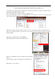
2 1.Overview Precautions When Using Kanomax Software Products on Windows 7 Stored data may not appear in Windows Explorer if you had saved data in the C:/ folder or the folders under the Program Files (Program Files(x86) for 64 bit). Click “Compatibility files” in Windows Explorer to display the data. If you can not perform this operation, or “Compatibility files” does not appear, you need to save data in the folder such as “My Document” which users can read or write.
3 1.Overview Table of Contents 1. Overview.............................................................................................................. 5 1.1. 1.2. 2. Packing List............................................................................................................................5 System Overview ...................................................................................................................5 Installation .....................................................
1.Overview 4 6.6.2. 6.6.3. 6.6.4. Particle Graph...................................................................................................................................28 Temperature, Humidity, Air Velocity and Differential Pressure Graph ............................................30 Data Table.........................................................................................................................................31 6.7. Other Functions .......................................
5 1.Overview 1. Overview 1.1. Packing List The following item is included in this package: 1. AIRBORNE PARTICLE COUNTER SOFTWARE CD-ROM QTY 1 If the CD-ROM is missing or damaged, please contact your local distributor immediately. 1.2.
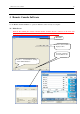
2. Installation 6 2. Installation 2.1. Installation When installing the software, be sure to log in with a user that has administrative rights and follow the procedure below. Insert the product CD-ROM into the CD-ROM drive. This operation can be started from the Windows Explore menu. (1) Using Windows Explorer, find and double-click the setup.exe file located in the “English” folder on the product CD-ROM. (2) Follow the instructions displayed on the screen.
2. Installation 2.3. Uninstalling (1) Open [My Computer] -> [Control Panel] -> [Add or Remove Programs]. (2) Select [PARTICLE COUNTER Software] from the list, and click [Remove].
8 3. Remote Console Software 3. Remote Console Software Use the Remote Console Software to operate the Particle Counter remotely via computer. 3.1. Main Screen Both the PC running the software and the Particle Counter must be connected to the LAN and properly configured in order to access the Particle Counter remotely via PC. Menu Bar Remote Screen will be displayed here. Connection Settings, Connect Buttons etc. Refer to “3.3.
3. Remote Console Software 9 3.2. Menu List File Menu [Exit] Closes the software. Help Menu [About] Views the software version information. 3.3. Destination Settings and Command Buttons (Refer to 3.1. Main Screen.) Host Name Enter the Host Name for the instrument you wish to connect with. The instrument’s Host Name is configured in the instrument’s COMMUNICATION SETTING. You can also choose a Host Name by using [Search] which will display all the instruments currently connected to the LAN (Refer to 3.
10 3. Remote Console Software 3.4. How to Operate the Remote Console Software Operation Screen . After the computer is successfully connected to the instrument, the instrument screen will be displayed on the computer. Click the buttons on the display to operate the instrument as described in the instrument’s instruction manual. Due to LAN communication lag, there may be a slight delay before the instrument reacts to your commands.
11 3. Remote Console Software 3.5. Search Function Click [Search] to find instruments connected to the LAN. Click [Search] If a connected instrument is found, it will be listed in the “Search Sensors” window shown above. Select the instrument that you want to connect with and click [Set]. The name of the instrument selected will be displayed on the Remote Console Software,File Transfer Software or User Management Software.
12 4. Scheduler Software 4. Scheduler Software Use the Scheduler Software to create a schedule file for use when performing a measurement. 4.1. Main Screen Map image will be displayed here. Location Information will be displayed here. 4.2. Menu List File Menu For file related operations. [New] Creates a new SCHEDULE file. [Open] Loads a saved SCHEDULE file. [Save] Saves a created SCHEDULE file. [Load Map] Loads a MAP image file. [Delete] Deletes a created SCHEDULE file.
13 4. Scheduler Software Location Menu [Edit Location] Edits the selected Location. [Delete Location] Deletes the selected Location. [Clear List] Deletes all Locations. [Up] Shifts the selected Location up one spot in the list. [Down] Shifts the selected Location down one spot in the list. Help Menu [About] Shows the software version information. 4.3. Command Buttons Zoom Magnifies the displayed MAP. Save Saves the SCHEDULE that you are editing. Open Opens the saved SCHEDULE file.
4. Scheduler Software 4.4. Schedule File Creation 4.4.1. Creating a new file (1) Click [File] -> [New], or Click [New]. (2) The “New Schedule” window will be displayed. Enter a Schedule name and specify a MAP File to load. To select a MAP File click [Ref] to display the “Select MAP File” window and click the file that you wish to use. Without a MAP file, you cannot create a Schedule with this application.
4. Scheduler Software 15 (3) To create a new measurement point click the place on the MAP where you wish to add a location. Then the “Edit Location” window will open. NAME: Enter a Location Name. Position: The coordinates that you clicked are displayed. You can edit these. ADDITIONAL INFO: Click on [Ref] to select an image file for ADDITIONAL INFORMATION. The image format should be *.jpg or *.bmp. [Zoom] button: Magnifies the image that was loaded in ADDITIONAL INFO.
16 5. File Transfer Software 5. File Transfer Software Use the File Transfer Software to download stored measurement data from or upload a schedule file to the Airborne Particle Counter. 5.1. Main Screen Both the PC running the software and the Airborne Particle Counter must be connected to the LAN and properly configured in order to access the Airborne Particle Counter remotely via PC. Configure connection settings Files will be displayed here. 5.2. Menu List File Menu [Exit] Closes the software.
5. File Transfer Software 17 5.3. Destination Settings and Command Button Host Name Enter the Host Name of the instrument you wish to connect with. The instrument’s Host Name is configured in the instrument’s COMMUNICATION SETTING. You can also choose a Host Name by using [Search] which will display all the instruments currently connected to the LAN (Refer to 3.5 Search Function). Connect Click [Connect] to connect to the instrument configured in Host Name.
5. File Transfer Software Download/Upload (Radio Button) Toggles Upload or Download mode. Download Downloads the selected data file. Upload Uploads the selected Schedule file to the instrument. EXIT Closes the software.
5. File Transfer Software 5.4. Downloading Measurement Data (1) Enter “Host Name” and click [Connect] to connect the computer with the instrument (Refer to 5.3 Destination Settings and Command Button). (2) Select the [Download] radio button. (3) Select the file that you want to download. The selected file name will be displayed under “File Name”. (4) Click [Download]. (5) The “Save As” dialogue box will be displayed. Enter a file name and click [Save].
5. File Transfer Software 5.5. Uploading a Schedule File (1) Enter “Host Name” and click [Connect] to connect the computer with the instrument (Refer to 5.3 Destination Settings and Command Button). (2) Select the [Upload] radio button. (3) Select the Schedule file that you want to upload. The selected file name will be displayed under “File Name”. (4) Click [Upload]. The schedule file is then uploaded to the instrument and the main screen will be displayed.
5. File Transfer Software 5.6 Search Function Refer to 3.5 Search Function.
22 6. Measuring Software 6. Measuring Software Use the Measuring Software to collect particle, air velocity, temperature, humidity and differential pressure data from the Airborne Particle Counter. Start-up Operation 6.1. Operation Overview * NOTE: The instrument must be placed in “REMOTE MODE” when running this program (Please refer to the instrument manual for further directions). (1) From the start menu, click :[(All) Programs] -> [KANOMAX] - > [Measuring Software].
23 6. Measuring Software 6.2. Screen Structure Menu bar and tool bar are displayed on the parent window. The menu bar and tool bar change depending on the active window. Tool Bar Particle Graph Window THVP Graph Window Data Table Window Status Bar Program Status: Sampling or Wait Sampling Time Interval No. of Sampling 1) Toolbar The menu items most commonly used are shown as icons on the toolbar. Click on the corresponding button to execute the item easily.
6. Measuring Software 24 6.3. Data File 6.3.1. File Menu New Start a new file using the current configured parameters (The default file name is “NEWFILE.KRM”). (If there is unsaved data, a dialog box appears asking if you want to save the data.) Open… Loads an existing file (If there is unsaved data, a dialog box appears asking if you want to save the data). Save Saves the current data under a file name you specify. Print Prints the graph or data in the active window.
25 6. Measuring Software 6.4. Settings 6.4.1. LAN Settings Click [Setting] -> [R LAN Setting…] to display the “LAN Setting” dialog box. Enter the Host Name of the instrument you wish to connect with and click [OK]. You can also set the Host Name using [Search] (Refer to 3.5 Search Function). 6.4.2. Measurement Parameter Settings Click [Setting] -> [Measurement Parameter Setting…] to display “Measurement Parameter Setting” dialog box.
6. Measuring Software 26 6.5. Remote Measurement NOTE: The instrument must be placed in “REMOTE MODE” when running this program. (Please refer to the instrument manual for further directions.) Both the PC running the software and the Airborne Particle Counter must be connected to the LAN and properly configured in order to access the Airborne Particle Counter remotely via PC. 6.5.1. Start/End Measurement 1) To Start a Measurement Click [Measurement] -> [Measurement] or the icon to start a measurement.
6. Measuring Software 27 6.5.2. Measurement Measurement Control: During a measurement, the program performs measurement timing control, turns the Airborne Particle Counter pump on and off, and downloads data. Data Display: During a measurement, you can display the time series graph and data table in real time. (Refer to 6.6 Remote Measurement Data Display.) 6.5.3. Measurement Data Storage Specify the destination to save data manually after measuring.
28 6. Measuring Software 6.6. Remote Measurement Data Display 6.6.1. Data Display Format The following table shows the display formats used by the Particle & THVP Graphs: Unit Particle p, p/cf, p/m3 Temperature Humidity Air Velocity deg C, deg F % m/s, FPM Display Format <10000 : XXXX ≧10000 : X. XXXE + X XXX. X XXX. X X. XXX Example 2568 1.256E + 5 26.5 75.3 0.652 6.6.2. Particle Graph To display the particle graph, go to [View] -> [Time Series Graph] -> [Particle] or click on the tool bar.
6. Measuring Software 29 2) Particle Graph Parameter Settings To edit the Particle Graph Parameter Settings, click [View] -> [Graph Parameter Edit] -> [Particle], or click on the tool bar to display the “Particle Graph Parameter Edit” dialog box shown on the right. Then configure the Particle Graph Parameter Settings.
30 6. Measuring Software 6.6.3. Temperature, Humidity, Air Velocity and Differential Pressure Graph To display the TVHP graph, go to [View] -> [Time Series Graph] -> [Particle] or click on the tool bar. 1) THVP Graph Window Only a linear type is available for the vertical axis for a THVP graph. T H V P : Temperature : Humidity : Air Velocity : Differential Pressure Temperature, Humidity, Air Velocity, and Differential Pressure data will be displayed from the left.
31 6. Measuring Software 6.6.4.Data Table Data values are listed in chronological order in the data table window. The window is resizable. Fig. Data Table Window To display the measuring data table, go to [View] -> [Data Table Display] or click on the tool bar.
6. Measuring Software 32 6.7. Other Functions 6.7.1. Switching Languages You can switch the language between English and Japanese by clicking [Option] on the menu bar. 6.7.2. Windows Arrange Click [Windows] -> [Windows Arrange] to display the graph windows and data table window. If [Standard Arrange] is checked, the graph and data table window will automatically resize when you change the main window size.
33 6. Measuring Software 6.7.4. Printing Function To print the current active graph or data list, click [File] -> [Print], or click on the tool bar.
7. Users Management Software 34 7.User Management Software Use the User Management Software to manage users, measurement data, and log data on the instrument. 7.1. When You First Start Software Both the PC running the software and the Airborne Particle Counter must be connected to the LAN and properly configured in order to access the Airborne Particle Counter remotely via PC. 7.1.1. Start Screen When the software starts, the “User Authentication” window will be displayed.
7. Users Management Software 7.1.3. Registering a New Local User When starting the software for the first time, be sure to register one or more local users with [Manage Users] right. To register a new local user, click [User] ->[Local], then click [Register].
36 7. Users Management Software After all user information and qualifications have been entered, click [OK] to register a new user or click [Cancel] to discard the current user data. The “User Management” window then appears, displaying a list of all currently registered users. If you wish to register another new user, click [Register]. You do not need to register all the users the first time you use the software. A user with [Manage Users] rights can register a new user at any time. 7.2.
7. Users Management Software If the password has expired, the “Set Password” window will be displayed. Enter the current password in the “Old password” box, and a new password in the “New password” and the “Confirm new password” boxes. Click [OK] to check the old password and save a new password. Then, the main screen will be displayed. Click [Cancel] to discard changes and return to the “User Authentication” window.
7. Users Management Software 38 7.2.2. Download Button The [Download] button transfers measurement data or log files from the instrument to the computer. The transferred data will be saved in the folder specified in [Data storage folder] (Refer to 7.1.2 Specifying Data Storage Folder and CF Card Drive Name). Click [Download] to display the “File Transfer” window. Enter the Host Name of the instrument you wish to connect to, and click the [Connect].
7. Users Management Software Under the “File Selection”, you can switch between [Data File] and [Log File]. Select a file to transfer, and click [Download]. When the download is finished, the message “The file has finished downloading” will be displayed. Click [OK]. To transfer another file, repeat the above procedure. When finished, click [Close] to exit the “File Transfer” window. A list of transferred files will be displayed.
7. Users Management Software 7.2.3. Decrypt Button A user with [Decrypt] rights can decrypt measurement data. Select a file to decrypt, and click [Decrypt]. Enter a file name and click [Save]. The data will be saved in CSV format.
41 7. Users Management Software 7.2.4. Approval1/Approval2 Button A user with [Approval1] or [Approval2] rights can approve measurement data. Select a file to approve, and click [Approval1] or [Approval2]. A dialog box appears asking if you approve. Click [OK] or [Cancel]. If you click [OK], your approval will be registered to the file. If you click [Cancel], the main screen will be displayed. 7.2.5.
7. Users Management Software ・Download Select a file, and click [Download] to start downloading. When the download is finished, the message “The file has finished downloading” will be displayed. Click [OK]. The user list is displayed and you can register a new user or edit existing users.
7. Users Management Software 43 ・Registering a new user Click [Register] to register a new user. You can specify user information and authorization settings. In the “Information” tab, enter: User Name (1 to 52 alphanumeric characters), User ID (4 to 16 alphanumeric characters), Password (4 to 16 alphanumeric characters), Confirm Password, Company/Division (up to 100 characters), Memo (up to 100 characters) (Reminder: Passwords expire every 180 days.
7. Users Management Software the user rights individually by checking off each box for the right(s) you wish to assign as shown to the right.
7. Users Management Software ・Edit To edit an existing user, select the user name and click [Edit]. The user information will be displayed. Edit the items as necessary, and click [OK] to save the changes or [Cancel] to discard the changes. ・Delete To delete an existing user, select the user name and click [Edit]. The user information will be displayed. Click [Delete] and a dialog box appears asking if you want to delete the user. Click [OK] to delete the user or [Cancel] to leave the user as is.
7. Users Management Software ・Upload To upload user data from a PC to an instrument click the [X] button on the user list window, to display the “File Transfer” window. (NOTE: The file transfer screen will only appear if you have registered a new user or edited an existing user. Otherwise you will be returned to the main screen when you close the user list window.) Enter the Host Name of the instrument you wish to connect with, and click [Connect].
7. Users Management Software 47 7.2.6. User Management [3910 SD Card] If the software is started by a user with [Manage Users] rights, you can register, edit, and delete user information stored on a SD(MMC) card. Click [User]->[3910 SD Card], a dialog box appears displaying drives specified in [Drive Name of SD(MMC) Card ]. (Refer to 7.1.2 Specifying Data Storage Folder and SD(MMC) Card Drive Name.) Select a user list file, and click [Open]. (By default this file is Users.dat located in the PARAM folder.
7. Users Management Software 48 7.2.7. User Management [Local] If the software is started by the user with [Manage Users] right, you can register, edit, and delete users registered in the PC. The user without [Manage Users] right can only change the password for logged-in users. [When the user with [Manage Users] right logs in] If you click [User]->[Local], the list of registered users will be displayed. ・Registering a new user Please refer to 7.1.3 Registering a New Local User.
7. Users Management Software ・Edit To edit an existing user, select the user name and click [Edit]. The user information will be displayed. Edit the items as necessary, and click [OK] to save the changes or [Cancel] to discard the changes. ・Delete To delete an existing user, select the user name and click [Edit]. The user information will be displayed. Click [Delete] and a dialog box appear asking if you want to delete the user. Click [OK] to delete the user or [Cancel] to leave the user as is.
7. Users Management Software Click the [X] button to close the user list window, and the main screen will be displayed. [When the user without [Manage Users] right logs in] If you click [User]->[Local], the edit window of logged-in users will be displayed. ・Edit You can only change passwords. Change a password when the password will expire soon. Click [OK] to save the changes or [Cancel] to discard the changes. ・Exit Click [OK] or [Cancel], and the main screen will be displayed.
8. Miscellaneous Notes 8. Miscellaneous Notes If you forgot the password(s) for all local users with [Manage Users] rights, please contact us for assistance.
USA & Europe KANOMAX USA, INC. PO Box 372, 219 Route 206, Andover, NJ 07821 U.S.A. TEL: 1-800-247-8887 / 1-973-786-6386 FAX: 1-973-786-7586 URL: http://www.kanomax-usa.com/ E-Mail: info@kanomax-usa.com Japan & Asia KANOMAX JAPAN, INC. 2-1 Shimizu Suita City, Osaka 565-0805, Japan TEL: 81-6-6877-0183 FAX: 81-6-6877-5570 URL: http://www.kanomax.co.jp/ E-Mail: sales@kanomax.co.jp China Shenyang Kano Scientific Instrument Co., Ltd No.