
Operating instructions


9.801-509.0 - D • Karcher Operator's Manual
MANUAL
PRESSURE WASHER
10
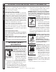
INSTALLATION
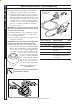
Install a gas union in the gas line adjacent to and up-
stream from the control manifold and downstream from
the manual main shut-off valve. A 1/8" NPT plugged
tapping accessible for test gauge connection shall
be installed immediately upstream of the gas supply
connection for the purpose of determining the gas
supply pressure to the burner, and to prevent damage
to gas valve.
If a manual gas shut off valve is not in the gas supply
line within six feet of the machine and in an accessible
location, one shall be installed.
Figure 1: Union Location
Union Connection
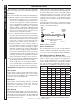
The following pipe sizes are just recommendations.
Always consult a local plumber and venting contrac-
tor for local codes and regulations during installation.
Pipe Sizing Chart for Natural Gas
The following chart is based on gas pressure in the
range 0-0.5 psi, specific gravity of 0.6 and pressure
loss of 0.5" W.C. Numbers are for straight schedule
40 pipe; fittings further reduce capacity. For example,
in 1" size, an elbow is equivalent to about 2.6 feet of
pipe and a tee is equivalent to about 5.2 feet of pipe.
Maximum capacity of pipe in cubic feet/hr of natural gas
(Multiply values by 1000 to get nominal BTU/hr capacity.
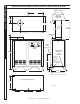
Place machine in a convenient location providing ample
support, drainage and room for maintenance (pgs 8-9).
Location:
The location should protect machine from damaging en-
vironmental conditions, such as wind, rain and freezing.
1. The machine should be run on a level surface
where it is not readily influenced by outside sourc-
es such as strong winds, freezing temperatures,
rain, etc. The machine should be located consider-
ing accessibility for the replacing of components
and the refilling of detergents, adjustments and
maintenance. Normal precautions should be taken
by the operator of the machine to prevent excess
moisture from reaching the machine.
2. It is recommended that a partition be made be-
tween the wash area and machine to prevent direct
spray from the spray gun from coming in contact
with the machine. Excess moisture reaching the
power unit or electrical controls will reduce the
machine’s life and may cause electrical shorts.
3. During installation of the machine, beware of
poorly ventilated locations or areas where exhaust
fans may cause an insufficient supply of oxygen.
Sufficient combustion can only be obtained when
there is a sufficient supply of oxygen available for
the amount of fuel being burned. If it is necessary
to install a machine in a poorly ventilated area, out-
side fresh air may have to be piped to the burner
and a fan installed to bring the air into the area.
4. Do not locate near any combustible material. Keep
all flammable material at least 20 feet away.
Allow enough space for servicing the machine.
Local code will require certain distances from floor
and walls. (Two feet away should be adequate).
WARNING: Avoid small areas or near exhaust fans.
Gas Codes:
Confer with local gas company and with proper mu-
nicipal officials regarding any specific code or regula-
tions governing the installation. The installation must
conform to local codes (NFPA 54).
Electrical:
The machine, when installed, must be electrically
grounded in accordance to local codes. Check for
proper power supply using a volt meter; check the
serial plate for the correct requirements.
Gas Piping:
This machine shall be rigidly connected to the gas pip-
ing outlet and equipped with external manual shut-off
valves adjacent to such machine. All gas piping shall
be approved and installed in accordance with the
Uniform Mechanical Code.
98015100-25
Manual
Shut-Off
Valve
1/8" NPT Plugged Pressure Gauge
Port Location
Union
Drop
Floor Level
Length of
Pipe (ft.)
Iron Pipe Size
3/4" 1" 1 -1/4" 1- 1/2" 2"
10 360 680 1400 2100 3950
20 250 465 950 1460 2750
30 200 375 770 1180 2200
40 170 320 660 990 1900
50 151 285 580 900 1680
60 138 260 530 810 1520
70 125 240 490 750 1400
80 118 220 460 690 1300
90 110 205 430 650 1220
100 103 195 400 620 1150
150 84 160 325 500 950
200 72 135 280 430 800