High pressure cleaner Combustion engine - Hot water Register your product www.kaercher.com/welcome English.....
MODELS: 1.575-555.0 HDS 2.8/25 P Cage 1.575-550.0 HDS 2.6/30 P Cage 1.575-551.0 HDS 3.5/30 P Cage 1.575-552.0 HDS 3.5/30 PE Cage 1.575-553.0 HDS 3.5/35 PE Cage 1.110-085.0 HDS 3.
CONTENTS Introduction & Important Safety Instructions 4-6 Component Identification 7 Assembly Instructions 8 Operating Instructions 9-10 Detergents and Cleaning Tips 11 Shut-Down and Clean Up 12 Storage 12 Maintenance 13-15 Troubleshooting 16-18 Maintenance & Oil Change Charts 19 Exploded View - 555.0 20 Exploded View - 550.0, 551.0, 552.0, 553.0 21-22 Exploded View Parts Lists 23-26 Control Panel - 555.0 & Parts List 27-28 Control Panel - 550.0, 551.0, 552.0, 553.
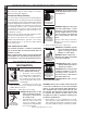
PRESSURE WASHER OPERATOR’S MANUAL INTRODUCTION & IMPORTANT SAFETY INFORMATION Thank you for purchasing this Pressure Washer. We reserve the right to make changes at any time without incurring any obligation. WARNING:This machine exceeds 85 db appropriate ear protection must be worn. Owner/User Responsibility: The owner and/or user must have an understanding of the manufacturer’s operating instructions and warnings before using this pressure washer. Warning information should be emphasized and understood.
Gasoline engines on mobile or portable equipment shall be refueled: a. outdoors; b. with the engine on the equipment stopped; c. with no source of ignition within 10 feet of the dispensing point; and d. with an allowance made for expansion of the fuel should the equipment be exposed to a higher ambient temperature. In an overfilling situation, additional precautions are necessary to ensure that the situation is handled in a safe manner. WARNING: Risk of injury.
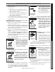
PRESSURE WASHER OPERATOR’S MANUAL IMPORTANT SAFETY INFORMATION WARNING RISK OF INJURY FROM FALLS WHEN USING LADDER. WARNING: Be extremely careful when using a ladder, scaffolding or any other relatively unstable location. The cleaning area should have adequate slopes and drainage to reduce the possibility of a fall due to slippery surfaces. 21. Do not allow acids, caustic or abrasive fluids to pass through the pump. 22. Never run pump dry or leave spray gun closed longer than 1-2 minutes. 23.
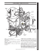
PRESSURE WASHER OPERATOR’S MANUAL COMPONENT IDENTIFICATION Gasoline Tank Discharge Nipple Detergent Injector Pressure Switch Unloader Collar Quick Coupler Water Supply Hose (not included) Pump Spray Gun Battery Box Wand Coupler Nozzle Quick Coupler Trigger Variable Pressure Control wand Brass Soap Nozzle Control Wand Handle High Pressure Hose Swivel Connector Pump — Develops high pressure. Starter Grip — (Not Shown) Used for starting the engine manually.
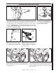
OPERATOR’S MANUAL PRESSURE WASHER ASSEMBLY INSTRUCTIONS Pressure Nozzle Soap Nozzle Safety Latch Spray Gun Wand Coupler Wand Coupler Wand Collar High Pressure Hose STEP 1: Attach the high pressure hose to the spray gun using teflon tape on hose threads. STEP 2: Pull the spring-loaded collar of the wand coupler back to insert your choice of pressure nozzle. DipStick STEP 3: Release the coupler collar and push the nozzle until the collar clicks. Pull the nozzle to make sure it is seated properly.
Oil Dipstick Gas Tank STEP 1: Check engine oil level. Oil level should be level with the bottom of the oil filler neck. Be sure the machine is level when checking the oil level. (Refer to the engine's operating manual included with machine.) We recommend that the oil be changed after the first 5 hours of use, then once every 50 hours. Note: Improper oil levels will cause low oil sensor to shut off engine. IMPORTANT! Do not run engine with high or low oil levels as this will cause engine damage.
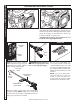
WASHER OPERATING INSTRUCTIONS OPERATOR’S MANUAL PRESSURE Throttle STEP 7: Turn the engine to "Run" position. STEP 8: Pull the starter grip. If the engine fails to start after 2 pulls, squeeze the trigger gun to release pressure and repeat step. Return starter gently. After the engine warms up enough to run smoothly, move choke to run position and throttle to fast position. CAUTION: Small engines may kick back. Do not hold pull starter grip tightly in hand.
WARNING: Some detergents may be harmful if inhaled or ingested, causing severe nausea, fainting or poisoning. The harmful elements may cause property damage or severe injury.
OPERATOR’S MANUAL PRESSURE WASHER SHUTTING DOWN AND CLEAN-UP On-Off Switch STEP 1: Remove detergent suction tube from container and insert into 1 gallon of fresh water. Turn variable pressure wand handle for low pressure or connect the black detergent nozzle. Pull trigger on spray gun and siphon water for one minute. STEP 2: Turn off the engine. Water Inlet STEP 4: Press trigger to release water pressure. STEP 3: Tur n off water supply.
PREVENTATIVE MAINTENANCE 1. Check to see that the water pump is properly lubricated. 2. Follow Winterizing Procedures to prevent freeze damage to the pump and coils. 3. Always neutralize and flush detergent from system after use. 4. If water is known to be high in mineral content, use a water softener in your water system or de-scale as needed. 5. Do not allow acidic, caustic or abrasive fluids to be pumped through system. 6. Always use our high grade quality cleaning products. 7.
PRESSURE WASHER OPERATOR’S MANUAL MAINTENANCE Fuel: Use clean fuel oil that is not contaminated with water and debris. Replace fuel filter and drain tank every 100 hours of operation. Use No. 1 or No. 2 Heating Oil (ASTM D306) only. NEVER use gasoline in your burner tank. Gasoline is more combustible than fuel oil and a serious explosion could result. NEVER use crankcase or waste oil in your burner. Fuel unit malfunction could result from contamination.
Wayne Burner Fuel Pressure Adjustment: To adjust fuel pressure, First install a pressure gage into the port just after the pump fuel exit. Turn the adjusting screw (located at the regulator port) clockwise to increase, and counterclockwise to decrease. Do not exceed 205 psi or lower the pressure below 130 PSI, when checked at the post-pump pressure port. The fuel pressure may need to be adjusted due to altitude. For every 500 ft altitude above sea level, the boiling point of water goes down 1 °F.
PRESSURE WASHER Troubleshooting Guide TROUBLESHOOTING PROBLEM POSSIBLE CAUSE SOLUTION LOW OPERATING PRESSURE Water supply is insufficient Use larger supply hose; clean filter at water inlet. Match the nozzle number to the machine and/or replace with new nozzle. Tighten or replace belt; use correct belt. Check plumbing system for leaks. Retape leaks with teflon tape. Adjust unloader for proper pressure. Install repair kit when necessary or replace. Install new packing kit.
PROBLEM POSSIBLE CAUSE SOLUTION BURNER WILL NOT LIGHT (continued from previous page) Burner nozzle is clogged Clean as required. Thermostat has malfunctioned Test and replace if needed. Fuel solenoid has malfunctioned Test and replace if needed. Fuel is improper or water is in fuel Drain tank and replace contaminated fuel. Air adjustment is improper Readjust air bands on burner assembly. Fuel pressure is low Adjust fuel pump pressure to specifications.
PRESSURE WASHER Troubleshooting Guide TROUBLESHOOTING PROBLEM POSSIBLE CAUSE SOLUTION DETERGENT NOT DRAWING Air is leaking Tighten all clamps. Check detergent lines for holes. Injector head may be blocked, dirty or damaged Clean and make sure ball and spring behind detergent hose barb or injector body are working properly. Filter screen on detergent suction hose is plugged Clean or replace. Detergent has high viscosity Dilute detergent to specifications.
PREVENTATIVE MAINTENANCE This pressure washer was produced with the best available materials and quality craftsmanship. However, you as the owner have certain responsibilities for the correct care of the equipment. Attention to regular preventative maintenance procedures will assist in preserving the performance of your equipment. Contact your dealer for maintenance. Regular preventative maintenance will add many hours to the life of your pressure washer.
OPERATOR’S MANUAL PRESSURE WASHER EXPLODED VIEW - 555.0 MODELS Reversed View of labels 17 Reversed View of label 101 3 60 116 6 74 5 10 145 1 115 2 8 11 25 23 22 94 107 24 47 118 13 46 2 58 17 61 70 27 2 14 114 57 97 141 156 155 28 29 130 26 53 89 90 64 154 134 141 52 53 96 120 15 111 63 133 49 53 37 38 56 16 19 49 121 For Detail See Control Box Illus. 37 18 45 For Brake Detail See Reversed View A-A (Enlarged) Pg.
Reversed View of labels 17 5 6 11 2 CH 2 8 AU D! 1 10 D! AU CH 3 3 74 115 61 14 58 116 114 60 13 92 71 17 PRESSURE WASHER OPERATOR’S MANUAL EXPLODED VIEW - 550.0, 551.0, 552.0, 553.0 MODELS 47 For Detail See Control Box Illus.
OPERATOR’S MANUAL PRESSURE WASHER EXPLODED VIEW - 550.0, 551.0, 552.0, 553.0 MODELS 550.
ITEM PART NO. DESCRIPTION 1 8.719-913.0 Top Hat, Coil 1 QTY 2 9.800-006.0 Label, Hot/Caliente w/Arrows Warning 3 3 9.802-825.0 Clip, Retaining, U-Type 4 4 9.198-004.0 3/8 USS F/W Zinc 4 5 8.925-220.0 8.919-133.0 Spare Coil, Dura SCH 80 MTY 15" DIA Coil Assembly (555.0) 1 1 6 8.919-732.0 8.919-733.0 Wrap, Outer Coil -07, Weldment (550.0, 551.0, 552.0, 553.0) Coil, Wrap, Outer, Weldment (555.0) 1 1 8 8.757-240.0 Manifold coil outlet discharge w/slnt 1 9 9.
PRESSURE WASHER OPERATOR’S MANUAL EXPLODED VIEWS PARTS LIST ITEM PART NO. 37 9.803-308.0 8.932-992.0 Mount, Rubber Vibration, 5/16", 70 Duro (555.0) Mount, Rubber Vibration, 3/8", 70 Duro (550.0, 551.0, 552.0, 553.0) QTY 4 4 38 9.802-064.0 Grommet, Rubber, Nozzle Holder 4 39 9.802-705.0 Bolt, 1/4" x 1" Carriage 4 40 Burner Assy, See Burner Spec's Page 40 41 9.802-809.0 Nut, 5/16" Wing (552.0, 553.0) 4 42 9.802-781.0 Nut, 3/8" Flange, Whiz Loc 4 43 8.757-205.
ITEM PART NO. DESCRIPTION QTY 75 9.800-002.0 Label, Use Only Kerosene 1 76 8.750-647.0 Grommet, Rubber, 1 1/2" (550.0, 551.0, 552.0, 553.0) 1 77 9.800-026.0 Label, Open For Steam (Steam Option) 1 78 9.802-010.0 Nipple, 1/4", Hex, Steel (Steam Option) 1 79 9.802-802.0 Washer, 1/4" Flat, SAE 12 80 9.802-187.0 Valve, Flow Control w/Metering (Steam Option) 1 81 9.802-120.0 Tee, 1/4" Branch Male, Legacy Pumps (Steam Option) 1 82 8.757-366.0 Nipple, 1/4" X 3", W/SLNT 1 83 9.
PRESSURE WASHER OPERATOR’S MANUAL EXPLODED VIEW PARTS LIST ITEM PART NO. DESCRIPTION 116 8.757-551.0 Elbow Street Steel 3/8" 45° 1 117 8.900-282.0 Label, RPM Factory Set 1 118 8.757-653.0 Nipple steel hex 3/8" NPTF x 3/8" BSPP (555.0) 1 119 9.802-811.0 Washer, Fender (555.0) 2 120 9.800-018.0 Label, Tipover Hazard 1 121 9.800-049.0 Label, Cleaning Solution 1 123 9.802-807.0 Washer 3/8", SAE Flat (550.0, 551.0, 552.0, 553.0) 4 124 9.802-744.0 9.802-741.
PRESSURE WASHER OPERATOR’S MANUAL CONTROL PANEL EXPLODED VIEW - 555.0 MODELS 24 4 6 5,25 18 22 20 10 7 9 29 30 31 17 3 9 1/10 UR HO 28 15 26 12 2 8 21 11 27 20 Reversed View 1 13 23 16 19 14 555.0 CONTROL PANEL PARTS LIST ITEM PART NO. DESCRIPTION QTY 1 9.802-528.0 Capacitor 1 2 9.802-531.0 Regulator, Voltage, 15 Volt 1 3 9.803-036.0 Box, Electrical 1 4 9.803-121.0 Assembly, Cover, Electrical Box 1 5 8.750-094.0 Thermostat, Adjustable, 302°F 1 6 9.802-456.
PRESSURE WASHER OPERATOR’S MANUAL 555.0 CONTROL PANEL PARTS LIST ITEM PART NO. DESCRIPTION 16 9.802-206.0 Clamp, Hose 1 17 9.802-791.0 Nut, Cage, 10/32" x 16 Gauge 2 18 8.900-907.0 Label, Control Panel 1 19 9.802-802.0 Washer, 1/4", Flat, SAE 1 20 9.802-695.0 Nut, 10/32" Keps 5 21 9.802-771.0 Screw, 10/32" x 3/4" 3 22 9.802-759.0 Screw, 10/32" x 1/2" 2 23 9.803-048.0 Cap, Capacitor, 1.37 x 1.50 x .060 Blk, w/o Hole 1 24 9.803-840.0 Label, Reset 25 9.802-447.
PRESSURE WASHER OPERATOR’S MANUAL CONTROL PANEL - 550.0, 551.0, 552.0, 553.0 1, 23 28 2 25 13 4 8 30 31 24 14 5 25 7 19 26 6 9 28 1/10 HOUR 15 21 10 22 19 27 16 3 29 16 18 17 11 12 20 550.0, 551.0, 552.0, 553.0 CONTROL PANEL PARTS LIST ITEM PART NO. DESCRIPTION 1 8.750-094.0 Thermostat, Adjustable, 302°F 1 2 9.803-035.0 Cover, Electric Box, Black 1 3 9.802-759.0 Screw, 10/32" x 1/2" BHSOC, Black 2 4 9.802-485.0 Breaker, 1658-G41-02-P10-25A 1 5 8.750-096.
PRESSURE WASHER OPERATOR’S MANUAL 550.0, 551.0, 552.0, 553.0 CONTROL PANEL PARTS LIST ITEM PART NO. 10 9.802-453.0 Switch, Curvette RA901VB-B-1-V, Carling 1 11 9.802-519.0 Strain Relief, 1/2" Metal, Two Screw 2 12 9.802-514.0 Strain Relief, Small 1 13 9.803-071.0 Box, Electric, Black 1 14 9.802-788.0 Nut, 5/16" Whiz Loc Flange 2 15 9.802-530.0 Rectifier, Bridge (552.0, 553.0) 1 16 9.802-470.0 Relay, P & B, VF4-41F11, 12VDC, 40AMP 2 17 9.802-528.
PRESSURE WASHER OPERATOR’S MANUAL HOSE & SPRAY GUN ASSEMBLY 5 7 6 1 2 8 3 4 Pressure Nozzle HOSE & SPRAY GUN PARTS LIST ITEM PART NO. DESCRIPTION 1 8.707-144.0 9.802-100.0 Nipple, 3/8", Female, Ssteel ▲ Quick Coupler O-Ring LG 1 1 2 8.925-130.0 8.925-132.0 Hose, 3/8" X 50' 1W 4000PSI SW/SO/CPL (All Models Except 553.0) Hose, 3/8" X 50' 2W 6000PSI SW/SO/CPL (553.0) 1 1 3 4.775-054.0 EASY! Force Advanced KNA 1 4 9.802-222.0 9.802-694.
PRESSURE WASHER DOWNSTREAM INJECTOR ASSEMBLY OPERATOR’S MANUAL 1 DOWNSTREAM INJECTOR PARTS LIST ITEM 1 PART NO. DESCRIPTION 8.756-797.0 8.756-796.0 INJECTOR, CHEMICAL, NON ADJ 0.083 (2.1MM) INJECTOR, CHEMICAL, NON ADJ 0.070 (1.8MM) 32 MANUAL, KARCHER, HDS 9.800-079.
1 PRESSURE WASHER OPERATOR’S MANUAL HOSE REEL OPTION 5 6 4 3 2 HOSE REEL PARTS LIST ITEM PART NO. DESCRIPTION QTY 1 8.707-144.0 Nipple, 1/4", Male, Ssteel 1 2 9.802-244.0 Hose, 3/8", 2 Wire Pressure Loop 1 3 9.802-269.0 Hose Reel, 100' Non-Pivot E-ZEE w/Pin Lock 1 4 9.802-767.0 Screw, 3/" x 3/4" HH NC, Whiz Loc 4 5 9.802-781.0 Nut, 3/8" Flange, Whiz Loc, NC 4 6 9.803-841.0 Bracket, E-ZEE Hose Reel Right, Wrinkle Black 1 33 MANUAL, KARCHER, HDS 9.800-079.
9.175-018.0 UU1 3500PSI, UNIVERSAL UNLOADER (SPARE) 21 14 2 21 3 20 10 OPERATOR’S MANUAL PRESSURE WASHER UU1 UNLOADER EXPLODED VIEW 16 18 5 1 15 19 6 27 7 25 23 25 4 24 8 22 27 28 26 13 15 26 12 17 27 23 9 11 UU1 UNLOADER EXPLODED VIEW PARTS LIST ITEM PART # 1 KIT QTY D 1 2 Piston C, D 1 3 Piston O-Ring Back Up A, D 1 4 5 6 8.751-394.0 Piston Housing Ball Seat 17 KIT QTY 9.149-006.0 Sliding Connector Guide 18 O-Ring Backup 6 x 1.45 x 1.
PRESSURE WASHER OPERATOR’S MANUAL VBT UNLOADER EXPLODED VIEW 8.754-696.0 UNLOADER, VBT BANJO 1/2M 3/8M, 3000PSI (SPARE) VBT UNLOADER EXPLODED VIEW PARTS LIST ITEM PART # DESCRIPTION KIT QTY ITEM PART # DESCRIPTION KIT QTY 1* 8.754-929.0 Stem C 1 17 9.803-914.0 Seal Washer 1/2) 1 2* 9.803-912.0 Backup Ring A 1 18 8.754-937.0 Bypass Manifold 1 3* 8.754-930.0 O-ring, Ø2.62 x 6.02 A 2 19 9.802-892.0 Outlet Connector 3/8 MPT 1 4 8.730-882.0 Stem Connector 1 20* 9.
8.751-194.0 KS3540GR.3 OPERATOR’S MANUAL PRESSURE WASHER KS3540GR.3 PUMP EXPLODED VIEW TORQUE SPECS Item # Ft.-lbs 14 75 15 30 24 7.6 38 10 KS3540GR.3 PUMP EXPLODED VIEW PARTS LIST ITEM PART NO. DESCRIPTION QTY ITEM PART NO. DESCRIPTION 1 8.751-217.0 Crankcase 1 26 8.717-225.0 O-Ring Ø 2.62 x61.6 QTY 1 2* See Kit Below Plunger Oil Seal 3 27 9.802-914.0 Snap Ring 1 3* See Kit Below O-Ring Ø1.78 x 31.47 3 28 9.803-168.
ITEM PART NO. DESCRIPTION QTY 50* See Kit Below O-Ring Ø1.78x5.28 3 51* See Kit Below Teflon Ring 3 52 8.751-225.0 Plunger Rod 3 53 8.751-228.0 Connecting Rod Pin 3 54 9.803-158.0 Connecting Rod 3 55 9.803-218.0 Spring Washer 6 56 9.803-238.0 Connecting Rod Screw 6 57 8.933-016.0 O-Ring 2.62 x 126.67 1 58 8.751-229.0 Crankcase Cover 1 59 9.803-197.0 O-Ring, Ø 1.78 x 14 1 60 9.803-202.
PRESSURE WASHER PUMP EXPLODED VIEW 23 47 23 24 25 26 27 28 OPERATOR’S MANUAL 41 30 29 18 17 16 15 12* 14 11* 18 46 37* 45 39* 38* 44 2* 4* 3 1 Item # Ft.-lbs 14 65 16 66 23 8 31 32 6* 8 43 TORQUE SPECS 5* 7* 35 40 36* 14 13* 22* 21* 12* 20* 19* 11* 42 33 34 9 35 10 35 8 36 9.5 43 12.5 13* PUMP EXPLODED VIEW PARTS LIST ITEM 1 PART NO. DESCRIPTION 8.754-841.0 Crankcase QTY ITEM 1 21* PART NO.
ITEM PART NO. DESCRIPTION 40 8.759-032.0 Plunger Rod 3 41 9.803-965.0 Connecting Rod Pin 3 42 9.803-966.0 Connecting Rod 3 43 8.933-020.0 Connecting Rod Screw 6 44 8.754-847.0 "O" Ring ø2.62X111.62 1 45 8.754-842.0 Crankcase Cover 1 46 9.803-906.0 "O" Ring ø1.78X14 1 47 9.803-202.
8.929-263.0 LPP3035G1 8.929-272.0 HPP3035G1 8.929-257.0 KPP3035G1 OPERATOR’S MANUAL PRESSURE WASHER LPP3035G1 PUMP EXPLODED VIEW TORQUE SPECS Item # Ft.-lbs 15 65 16 55 24 8 40 10 43 10 50 10 LPP3035G1 PUMP EXPLODED VIEW PARTS LIST ITEM 40 PART NO. DESCRIPTION QTY ITEM Crankcase 1 21 See Kits Below Valve Spring 6 PART NO. DESCRIPTION QTY 1 8.754-841.0 2* See Kits Below Plunger Oil Seal 3 22 See Kits Below Valve Cage 6 3 8.758-216.0 Spacer 1 23 9.802-939.
ITEM PART NO. DESCRIPTION QTY 40 9.803-218.0 Washer, 6 mm 10 41 8.754-864.0 Flange, Engine 1 42 8.754-855.0 Bolt, Plunger 3 43 8.754-092.0 Spacer, Copper 3 44 8.754-849.0 Plunger, 14 mm 3 45 9.803-962.0 Spacer, Copper 3 46 8.759-032.0 Plunger Rod 3 47 9.803-965.0 Connecting Rod Pin 3 48 9.803-966.0 Connecting Rod 3 49 8.933-020.0 Screw, Connecting Rod 6 50 8.754-847.0 O-ring Ø2.62 X 111.62 1 51 8.754-842.0 Cover, Crankcase 1 52 9.803-906.0 O-ring Ø1.
17 34 26 18 13 35 12 EXPLODED VIEW 21 15 7 11 50 2 30 23 24 5 4 3 6 STATIC DISC 17 26 17 (.125) 50 7 50 11 1 (.33) 7 (14.06) 12 GUN ASSEMBLY (.675) 13 23 23 24 24 42 MANUAL, KARCHER, HDS 9.800-079.0 5 6 4 2 3 (10.44) 50 ASSEMBLED VIEWS 30 4 6 30 2 4 6 5 3 30 OPERATOR’S MANUAL (10.39) 2 7 13 24 1 PRESSURE WASHER WAYNE BURNER EXPLODED VIEW (HDS 2.
Replacement Parts For best performance specify genuine MSR WAYNE replacement parts ITEM PART NO. DESCRIPTION QTY 1 8.759-188.0 Tube/Hous-101393-001/3A/3.75"/.88"I 1 2 8.756-437.0 Pump-Combo/W Solenoid 12V/24V 1 3 8.758-287.0 Fitting, Elbow 90* Street 1/8 1 4 8.758-286.0 Tee,Street-1/8 x 1/8 Brass 1 5 8.756-284.0 Connector, Male-3/16" x 1/8" IPT 1 6 8.758-285.0 Plug, Pipe HXHD 1/8" NPT 1 7 9.107-507.0 Ignitor-MSR 12V LA 1 11 8.759-189.
Replacement Parts WIRING DIAGRAM For best performance specify genuine EHASR WAYNE replacement parts 16 16 1 2 29 28 44 MANUAL, KARCHER, HDS 9.800-079.0 (14.41) 30 1 28 27 15 15 12 4 3 4 3 (12.29) 1 (.88) 4 20 28 (11.67) 3 30 12 11 OPERATOR’S MANUAL PRESSURE WASHER WAYNE BURNER PART LIST (3.5/30 P; 3.
Replacement Parts For best performance specify genuine EHASR WAYNE replacement parts ITEM PART NO. DESCRIPTION QTY 1 8.759-192.0 Tube/Hous-101407-001/3A/.88I 1 2 8.756-731.0 Gun-RG/*CST/GBB 1 3 8.756-437.0 Pump-s A2VA3006-N261 12V Combo 1 4 8.700-704.0 Oil Line ASM-6" 1 11 8.759-129.0 Plate Slot Cover 1 12 8.759-193.0 Nut, Hex 3/8-24 CRZC 1 15 8.700-732.0 Band, Air-Inner E/FH 1 16 8.700-729.0 Band, Air-Outner 8-Hole E/F 1 18 8.759-194.
PRESSURE WASHER Specifications SPECIFICATIONS BURNER SPECIFICATIONS Model # Fuel Pump/ Fuel Pump/ Burner Assy # Fuel Nozzle Transformer Burner Motor Solenoid Cord Solenoid Coil Electrode 1.575.555.0 8.756-655.0 8.756-723.0 9.107-507.0 8.700-821.0 8.756-437.0 8.756-437.0 8.756-297.0 1.575-550.0 8.756-655.0 8.756-916.0 9.107-507.0 8.700-821.0 8.756-437.0 8.756-437.0 8.756-297.0 1.575-551.0 8.756-756.0 8.756-699.0 9.107-507.0 8.756-716.0 8.756-437.0 8.756-437.0 8.756-731.0 1.
C METER 12VDC HOUR + _ 0 27 BURNER SWITCH 1 5 TH 23 5 AT 16 ERM S T O 200 OFF BURNER LAMP 2 0 300 13 MANUAL, KARCHER, HDS 9.800-079.0 86 86 A 30 RELAY 87A 87 30 RELAY 87A 87 85 85 CONTROL PANEL B _ + CIRCUIT BREAKER BATTERY ENGINE STARTER AC RECTIFIER AC R W RELAY/RECTIFIER W VANGUARD Y WIRE HONDA GR WIRE NOTE: FROM ENGINE GR GR PRESSURE WASHER Specifications WIRING DIAGRAM - HDS 3.5/30 PE AND HDS 3.
MANUAL, KARCHER, HDS 9.800-079.0 BURNER MOTOR 12VCD FUEL SOLENOID (SHUT-OFF VALVE) 12-24VDC IGNITOR 12 VCD CAD CELL PUR WHT RED BLK + RED BLK - PHOTOCELL GROUND TO BURNER HOUSING xt9 WITH SCREW W O BLK RED RED YLW YLW N.O. + RED - BLK WHT MACHINE CONNECTION 62411-052 12 GA FROM NUT 13743 16 GA FROM NUT COM RELAY 62411-053 12 GA FROM NUT RED BLK TIMER - 3 SEC A B C ALL WIRES BLACK UNLESS NOTED W-WHITE G-GREEN R-RED Y-YELLOW BL-BLUE GR-GREY 4.
MANUAL, KARCHER, HDS 9.800-079.0 BURNER MOTOR 12VCD FUEL SOLENOID (SHUT-OFF VALVE) 12-24VDC IGNITOR 12 VCD CAD CELL YLW PUR WHT RED BLK + RED BLK - PHOTOCELL GROUND TO BURNER HOUSING xt9 WITH SCREW W O BLK RED RED 1 YLW + RED BLK - 30 87A RELAY 87 30 87A RELAY 87 MACHINE CONNECTION 62411-052 12 GA FROM NUT WHT FLOW SWITCH 13743 16 GA FROM NUT COM RELAY N.O.
THANK YOU! ! MERCI! DANKE! GRACIAS! vielen Vorteilen. advantages. avantages. Registre su producto y aproveche de muchas ventajas. www.kaercher.com/welcome Bewerten Sie Ihr Produkt und sagen Sie uns Ihre Meinung. Rate your product and tell us your opinion. Évaluer votre produit et dites-nous votre opinion. Reseñe su producto y díganos su opinión. www.kaercher.com/dealersearch Alfred Kärcher SE & Co. KG Alfred-Kärcher-Str. 28-40 71364 Winnenden (Germany) Tel.