
Instructions


10 | DE
Aufstellung & Wandmontage
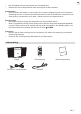
Sie können Sie Anlage entweder mit dem mitgelieferten Standfuß aufstellen (Option A) oder diese an
einer geeigneten Wand montieren (Option B):
26 | EN
Placement & Wall Mounting
You can either set up the unit on the supplied stand (option A) or mount it on a suitable wall (option B):
Wall Mounting (Option B)
result in severe personal injury and property damage (if you intend to install this product
yourself, you must check for installations such as electrical wiring and plumbing that
may be buried inside the wall). It is the installer’s responsibility to verify that the wall will
safely support the total load of the unit.
• Additional tools (not included) are required for the installation.
• Do not overtighten screws.
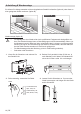
1. Remove the screws from the main unit.
2. Drill 2 parallel holes (Ø 3-8 mm each accord-
ing to wall type) in the wall. The distance
between the holes should be 121 mm.
Wall
3.
if necessary.
Drywall, plaster wall,
lath wall, etc.
Solid wall (e.g. brick,
concrete, wood)
Dowel
4. Leave a 5 mm gap between the wall and the
screw’s head. Lift the unit with the attached
wall brackets over the heads of the screws
and slot into place.
Option - A Option - B
Wandmontage (Option B)
• Die Montage an einer Wand sollte durch qualiziertes Fachpersonal durchgeführt wer-
den. Eine falsche Montage kann zu Beschädigungen und Personenschäden führen (vor
der Montage muss die Wand auf darin verlaufende Kabel, Leitungen und Rohre geprüft
werden). Es liegt in der Verantwortung des Nutzers, sicherzustellen, dass die Wand, an
der das Gerät montiert werden soll, hierfür auch geeignet ist.
• Die Wandmontage erfordert Werkzeug (nicht im Lieferumfang enthalten).
• Schrauben nicht überziehen.
1. Lösen Sie die Schrauben und nehmen Sie
den Standfuß ab.
26 | EN
Placement & Wall Mounting
You can either set up the unit on the supplied stand (option A) or mount it on a suitable wall (option B):
Wall Mounting (Option B)
result in severe personal injury and property damage (if you intend to install this product
yourself, you must check for installations such as electrical wiring and plumbing that
may be buried inside the wall). It is the installer’s responsibility to verify that the wall will
safely support the total load of the unit.
• Additional tools (not included) are required for the installation.
• Do not overtighten screws.
1. Remove the screws from the main unit.
2. Drill 2 parallel holes (Ø 3-8 mm each accord-
ing to wall type) in the wall. The distance
between the holes should be 121 mm.
Wall
3.
if necessary.
Drywall, plaster wall,
lath wall, etc.
Solid wall (e.g. brick,
concrete, wood)
Dowel
4. Leave a 5 mm gap between the wall and the
screw’s head. Lift the unit with the attached
wall brackets over the heads of the screws
and slot into place.
Option - A Option - B
2. Bohren Sie 2 parallele Löcher (Ø 3-8 mm, je
nach Wandart) in die Wand. Der Abstand zwi-
schen den Löchern sollte 121 mm betragen.
Wand
3. Falls notwendig, verwenden Sie Dübel.
Trockenbauwand,
Gips, Putz, etc.
Solide Wand (z. B.
Stein, Beton, Holz)
Dübel
4. Lassen Sie die Schrauben ca. 5 mm aus der
Wand herausragen und hängen Sie das Gerät
an die Schrauben.