Industrial stationary vacuuming systems Planning Manual English 5.906-587.0 Rev.
English 5.906-587.0 Rev.
Contents 1 Safety instructions 5 1.1 5 Hazard levels 2 When is a central vacuuming system used? 5 3 Target groups for a central vacuuming system 5 4 Advantages of a stationary vacuuming system 5 5 Abstract of the system planning 5 6 Components of a stationary vacuuming system 5 6.1 6.2 6.3 6.4 6.
17.1 17.2 17.3 17.4 Selecting the setup location Installation Functional description Parameter IV vacuum cleaner control 18 Annex 1 - Questionnaire central vacuuming systems 5.906-589.0 18.1 Customer details 18.1.1 Preface 18.2 Checklist product 18.3 Checklist system 18.4 Other information 30 30 30 30 31 31 31 31 32 33 19 Annex 2 - Motor characteristics 34 20 Annex 3 - Pipe programme 35 4 English 5.906-587.0 Rev.
1 Safety instructions 1.1 Hazard levels CAUTION Possible hazardous situation that could lead to mild injury to persons or damage to property. Note Indicates useful tips and important information. 2 – – – – – – – – 3 When is a central vacuuming system used? If the area to be vacuumed is locally fixed. If there is little space available at the working area. If the working areas are laid out over a large area and several vacuuming points are therefore required.
7 Prerequisite system planning Clarify with the customer in detail which requirements the stationary system should fulfil. The questionnaire for central vacuuming systems 5.906-589.0 helps, see Chapter "Annex 1 - Questionnaire central vacuuming systems 5.906-589.0“. – The system design is based on the number of suction stations to be operated in parallel and the amount of material to be transported per vacuuming point. – 8 8.
Area paper, plastics Vacuumed material Air speed Scrap of paper 15-22 m/s Rubber dust 18-20 m/s Trimming suction 16-18 m/s Swarf leather 15-16 m/s Paint mist spray booth 14-16 m/s Shorter textile fibres 12-16 m/s Foamed polystyrene (expanded polystyrene) 8-10 m/s Area minerals Vacuumed material Air speed Coarse dry sand without gravel 18-20 m/s Sandblasting, fettling shop 16-18 m/s Swarf glass 16-18 m/s Emery, corundum 116-18 m/s Sand 14-16 m/s Finest dry sanddust 12-14 m/s Oth
.2 Route planning Note The objective is to keep the resistance in the pipeline system as small as possible. – – – – – – – – – – – – – – Always choose the shortest possible way. Course as straight as possible with as few cracks and bends as possible. Use of the ways of other supply runs e.g. of present pipelines, cable runs etc. No obstruction of ways or systems. Provide for easily accessible cleaning opening. Optimum installation height is 2-3 m.
Calculation tool The calculation tool can be called up online via the DISIS and in SAP under the part number 5.906-608.0. 9.1 1 2 3 4 5 6 Calculation tool pipeline system Auxiliary tool for the conversion of units and calculator Selection "flow rate" Selection "Air volume flow" Selection "Inner pipe diameter" Input fields Button "Calculate" English 5.906-587.0 Rev.
9.1.1 Modes of calculation Calculation of the air speed 1 Selection "flow rate" 2 Input field "Air volume flow" 3 Input field "Inner pipe diameter" 4 Button "Calculate" Fill in input fields with relevant values. Press the "Calculate" button. The value of the air speed is displayed. 10 English 5.906-587.0 Rev.
Calculation of the air volume flow 1 Selection "Air volume flow" 2 Input field "flow rate" 3 Input field "Inner pipe diameter" 4 Button "Calculate" Fill in input fields with relevant values. Press the "Calculate" button. The value of the air volume flow is displayed. English 5.906-587.0 Rev.
Calculation of the inner pipe diameter 1 Selection "Inner pipe diameter" 2 Input field "flow rate" Depending on the material (see tabular values) 3 Input field "Air volume flow" Depending on the suction performance from the technical data sheet of the selected vacuum cleaner 4 Button "Calculate" Fill in input fields with relevant values. Press the "Calculate" button. The value of the inner pipe diameter is displayed. 12 English 5.906-587.0 Rev.
9.1.2 Conversion of units 9.1.3 Calculator Overview 1 2 3 4 Input field convert value "from" Display field convert value "into" Selection of the units "from" Selection of the units "into" Convert units "from" Auxiliary tool for the calculation of various values. Overview of the units Convert units "into" Overview of the units Select unit "from". Select unit "into". Enter the value into the input field, the conversion value is automatically shown in the display field. English 5.906-587.0 Rev.
9.2 Calculation tool calculation of the pressure loss 1 Loss coefficient or also pressure loss coefficient, pressure loss coefficient, drag coefficient is denominated with factor here. 2 The mass flow rate indicates the mass of a medium that moves through a cross section within a period of time. The mass flow rate is also referred to as flow rate. As a standard, it can be calculated with 1.0 here. 3 Air is the carrier gas.
10 Calculation of the pressure loss In an ideal line network no losses would occur and the necessary suction unit could be determined with the two parameters air speed and volume flow. In the real line network, however, losses are created due to resistances and turbulences. These must be calculated as pressure losses in the pipeline network in order to determine the required suction performance. With branched pipelines only the way that causes the greatest pressure loss (main run) must be determined.
10.1 Pressure loss calculation with the calculation tool 1 Button "Calculate" 2 Button "Adopt value" If all relevant data has been entered, the pressure loss of the section can be calculated by pressing the calculate button. With the "Adopt value" button the value can be loaded into a cache. The cache automatically adds up the adopted values. When all sections of the main run are calculated, the overall pressure loss is fixed. 16 English 5.906-587.0 Rev.
10.2 Addition of the sections 1 2 "Reset" button "Print" button With the "Reset" button all data is deleted. An overview can be printed via the "Print" button. 10.3 Alignment with vacuum cleaner characteristic The overall pressure loss is aligned with the vacuum cleaner characteristic to determine the actual volume flow. In the shown example, an overall pressure loss of 27 mbar was reached. With this value the volume flow of the vacuum cleaner is still 468 m³/h.
11 Sample calculation for the dimensioning of the vacuum cleaner In this example calculation, a suction unit for a shop with 3 work stations is to be designed. The system is to be designed in a way that 2 vacuuming points can be operated in parallel respectively. Plastic granules are to be vacuumed up. A Section: DN 80, 25 m, 3x Y-pieces, 2x 90° bends B Section: DN 60, 5 m C Section: DN 50, 5 m suction hose Note If they are not in operation, all branch lines are shut off by means of a slide or a flap.
11.5 Step 5 Calculation of the pressure losses in the sections: Note All sections together reveal the entire pressure loss plus 10-20% security. Example: Section Suction hose Lengt h Component Flow speed Pressure loss 1 DN 80 25 m 3x Y-pieces 2x 90° bends 27.63 m/s 32.63 mbar 2 DN 60 5m 24.56 m/s 6.03 mbar 3 DN 51 5m 35.37m/s 18.01 mbar 1x custom component (Suction hose) 110.94 mbar + 15% security addition = ~128 mbar 11.
11.7 Step 7 11.9 Step 9 Recalculation of the volume flow per vacuuming point. The recalculation takes place analogously to the previous example. Example: IV 100/55 as per technical data sheet with a pressure loss of 128 mbar = ~330 m³/h. With 2 vacuuming points the following applies: Volume flow per vacuuming point: 330m³/h / 2 vacuuming points = 165 m³/h per vacuuming point.
Step 4 Calculation of the pressure losses in the sections: Section Suction hose Lengt h Component Flow speed Pressure loss 1 DN 80 25 m 3x Y-pieces 2x 90° bends 30.39 m/s 46.13 mbar 2 DN 60 5m 27.02 m/s 7.30 mbar 3 DN 51 5m 38.90 m/s 15.00 mbar 1x custom component (Suction hose) 68.43 mbar + 15% security addition = ~79 mbar Step 5 Alignment with characterisitc. Example: With a pressure loss performance of 79 mbar, a volume flow of ~420 m³/h remains with IV 100/75. English 5.906-587.
Step 6 Recalculation of the volume flow per vacuuming point. Example: With a pressure loss performance of 79 mbar, a volume flow of ~420 m³/h remains with IV 100/75. Volume flow per vacuuming point: 420m³/h / 2 vacuuming points = 210 m³/h per vacuuming point. Step 7 Calculation of the actual flow velocities in the sections and subsequent alignment with the necessary air speed of the application: Example: Section Suction hose Volume flow rate Flow speed 1 DN 80 420 m³/h 23.
12 Basics of the system installation 12.1 Overview module components 1 2 3 4 5 6 7 8 9 10 11 12 13 Outlet tube Clack valve / false air flap Control cable Tensioning ring Y-branch Fastening clamp Pipe bend Control / distribution box Connection hose DN 70 Connection piece hose Cone piece Gate valve electrical or pneumatic Remote control English 5.906-587.0 Rev.
12.2 Examples for correct and incorrect system installation 12.3 Examples for the correct and incorrect branchings in the pipeline network 24 English 5.906-587.0 Rev.
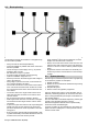
13 Use and setting of the false air valve Note A false air valve or a bypass valve is a valve that opens at a certain adjustable negative pressure in order to be able to vacuum with a constant air volume. 1 Locknut The adjustment is made via the lock nut. The valve is to be adjusted in a way that it does not open with all vacuuming points operated in parallel yet. A Induction pipe B False air / bypass valve C Silencer Suction performance per ~ 250 m³/h per vacuuming point Vacuum cleaner, performance e.
14 Installation instructions for tension ring connections with flanged sealing ring QUICK CONNECT© tension ring Mount the flanged sealing ring onto one of the flanged edges. The flanged sealing ring can be slightly pulled during mounting, however, do not overstretch it. Push the second tension ring half over the flanged edges. Flanged sealing ring mounted. Note The corrugated side of the flanged sealing ring must point towards the connection pipe part. Attach tension ring.
CAUTION – When closing the tension ring, the flanged sealing ring must not form a loop. In order to facilitate the closing process, the tensioning screw at the joint can be screwed back if necessary. – Then the tensioning screw must be tightened to prevent accidental unlocking of the joint (e.g. in case of vibrations) and to increase the tightness. – For explosion-proof connections up to 3 bar overpressure a tightening torque of 10 Nm is required.
15 Producing a flanged edge 15.1 Information concerning border sealings Profile for 1 mm Profile for 2 mm in: in: EPDM conductive NBR, silicone, Viton Measure the fitting length and transfer it to the pipe (fitting length + 7 mm for the flanged edge). Set the flanging device with the edge to this length and mark the cutting line over the circumference of the pipe. Push back the flanging device and cut the pipe to length using a cutoff wheel or a saw.
16 General mounting instructions for the creation of tight connections Note Border sealings made of NBR (nitrile rubber) are suitable for the use in the food sector (FDA approval available). In the area of explosive gases and dusts the earthing of all pipeline parts must be checked after the installation. Conductive border sealings made of EPDM do not make conductive connections with primed pipe parts due to the insulating paint. – – – – – – – Refinish damaged flanged edges (e.g. realign).
17 Commissioning remote control 17.1 Selecting the setup location Make sure that a suitable power supply is available in the immediate vicinity (see technical data of the vacuum cleaner). Note – The scope of delivery does not include any fastening material! – The fastening material must be adapted to the local consistency and condition of the wall and must be ordered separately. – You will need: 4 x suitable fasteners with a load of 0.5 KN per dowel and a pin diameter of max. 6 mm. 17.
18 Annex 1 - Questionnaire central vacuuming systems 5.906-589.0 18.1 Customer details Company name Date Address Telephone Customer number Fax Contact person E-mail Industry 18.1.1 Preface When selecting an industrial cleaning machine, two basic things have priority: For one thing the zoning in which the appliance is to be set up later on, and for another thing the type of the vacuumed material.
18.3 Checklist system Location of the vacuum cleaner Size of the plant room Temperature at the location °C Operating time of the plant Number of vacuuming points Number of vacuuming points operated in parallel Piping length m Vacuuming height m Length suction hose m Diameter suction hose Product discharge Automatic Manual Flap pneum.
18.4 Other information English 5.906-587.0 Rev.
19 Annex 2 - Motor characteristics 34 English 5.906-587.0 Rev.
20 Annex 3 - Pipe programme Welded pipes Nominal length Material Ød S Weight kg Part no. The pipe length and the diameter DN are nom- Ø60 inal dimensions, the actual length can differ. 2000 zinc-coated 57 1,5 4,34 6.880-017.0 1000 zinc-coated 57 1,5 2,10 6.880-025.0 500 zinc-coated 57 1,5 1,03 6.880-033.0 200 zinc-coated 57 1,5 0,45 6.880-041.0 2000 stainless steel 57 1,5 4,50 6.880-021.0 1000 stainless steel 57 1,5 2,24 6.880-029.
Welded pipes Nominal length Material Ød S Weight kg Part no. 500 stainless steel 119 1 1,49 6.880-040.0 200 stainless steel 119 1 0,63 6.880-048.0 50 stainless steel 119 1 0,18 6.880-054.0 Flanging device ØA Powder-coated flanging device with a welded on angle. For attaching a flanged edge to a pipe end. Ø60 60 Weight kg Part no. 3,10 6.880-161.0 3,30 6.880-162.0 3,60 6.880-163.0 4,70 6.880-164.
Jointring Material Jointrings for sealing insertion pipes at 1 to 3 mm wall thickness. Keltan (EPDM*/**) -30°C to +120°C; black. Ø60 EPDM Ød ØA Weight kg Part no. 7 53 0,01 6.880-072.0 9 68 0,02 6.880-073.0 9 87 0,02 6.880-074.0 9 106 0,03 6.880-075.0 Ø80 EPDM Ø100 EPDM Ø120 EPDM Pipe bends Angle Material Ød R S Weight kg Part no. Pipe bends with R=2D made of drawn halfshells. In use this means a flow optimisation and a larger wear resistance.
Pipe bends Angle Material 15° Ød R S Weight kg Part no. stainless steel 120 155 1 0,15 6.880-081.0 30° stainless steel 119 240 1 0,80 6.880-089.0 45° stainless steel 119 240 1 1,15 6.880-097.0 90° stainless steel 119 240 1 2,20 6.880-105.0 Pipe bow 90° Material Part no. R=500, Ø d=80. stainless steel 6.880-106.0 Fork piece 45° Material G H L S Weight kg Part no. 115 115 145 1,5 0,60 6.880-107.0 stainless steel 115 115 145 1,5 0,60 6.880-111.
Conical fork pieces 30° Material ØC ØE= ØF G H Weight kg Part no. 78 57 170 170 0,95 6.880-117.0 stainless steel 78 57 170 170 0,95 6.880-123.0 100 78 237 236 1,25 6.880-118.0 stainless steel 100 78 237 236 0,25 6.880-125.0 100 100 239 248 1,35 6.880-119.0 stainless steel 100 100 239 248 1,35 6.880-126.0 120 120 256 258 1,50 6.880-121.0 stainless steel 120 120 256 258 1,50 6.880-128.0 Material Ød A B S Weight kg Part no.
Hose connecting pieces Material Wall thickness 1 mm Ø60 Ød stainless steel 57 B F 60 L Weight kg Part no. 80 0,02 6.880-144.0 Ø80 zinc-coated 78 78 15 88 0,02 6.880-142.0 stainless steel 78 78 15 88 0,02 9.982-624.0 100 95 15 100 0,25 6.880-143.0 stainless steel 100 95 15 100 0,25 9.982-661.0 Ø100 zinc-coated Outlet pipes 45° with bird screen Material Ød A L Weight kg Part no. Bird screen Mesh 20 x 20 x 20 mm. Ø80 78 280 200 0,90 6.880-147.
Quick Connect tension rings, one-piece Material ØA ØB Weight kg Part no. Quick Connect tension rings without sealing compound for border sealings with 1 mm and 2 mm pipe parts. Ø80 100 80 0,35 9.982-818.0 stainless steel 100 80 0,35 6.880-003.0 123 103 0,35 9.982-834.0 stainless steel 123 103 0,37 6.880-004.0 143 123 0,40 9.982-843.0 stainless steel 143 123 0,40 6.880-005.0 Tension rings one-piece with sealing compound Material ØA ØB Weight kg Part no.
Border sealings Material ØA ØB Weight kg Part no. Border sealings for 1 mm (for QUICK CONNECT tension rings and two-piece tension rings without seal). Perbunan (NBR*) -30°C to +100°C; off-white Keltan (EPDM*/**) -30°C to +120°C; black Ø60 NBR 57 69 0,02 9.982-923.0 EPDM 57 69 0,02 6.880-013.0 NBR 81 93 0,02 6.880-010.0 EPDM 81 93 0,02 6.880-014.0 NBR 103 115 0,03 9.982-928.0 EPDM 103 115 0,03 6.880-015.
Pipe clamps wall mount Material ØA B C E Weight kg Part no. Pipe clamps for wall mount with insulation insert (EPDM, -40 °C – +120 °C). Use of the pipe clamps only for the absorption of transverse forces of the pipe. Ø60 zinc-coated 60 50 100 20x1 0,20 6.880-165.0 stainless steel 60 50 100 20x1 0,20 6.880-169.0 zinc-coated 80 64 138 30x2.5 0,70 6.880-166.0 stainless steel 80 64 138 30x2.5 0,70 6.880-170.0 zinc-coated 102 75 138 30x2.5 0,80 6.880-167.
Beam clamps Material Beam clamps for fixing pipelines to steel gird- Ø60 ers (without welding or drilling). zinc-coated With adjusting screw M10, D=11 mm and width stainless B=21 mm. steel ØA B C E Weight kg Part no. 60 50 100 20x1 0,20 6.880-181.0 60 50 100 20x1 0,20 6.880-182.0 Mounting bracket Material Part no. Mounting bracket zinc-coated. Load capacity 3.0 kN with 5 mm deformation. zinc-coated 6.880-183.0 Threaded rods Material Threaded rods 1000 mm long, DIN 975.
Hexagon nuts and washers Material Description Part no. Hexagon nuts DIN 934 zinc-coated Hexagon nut M10 7.311-006.0 zinc-coated Hexagon nut M12 7.311-008.0 stainless steel Hexagon nut M10 7.311-066.0 stainless steel Hexagon nut M12 7.311-071.0 zinc-coated Washer 10-200HV-A3E 7.312-005.0 zinc-coated Washer 12-200HV-A3E 7.312-008.0 Washers ISO 7090 Dowel Squeezing valve incl. installation material stainless steel Washer 10-A4 7.312-014.0 stainless steel Washer 12-A2 7.312-054.
Ball tap Material Part no. Ball tap with lever handle 2". chrome-plated 9.980-036.0 Hose clamps Ø in mm Part no. 40 - 60 6.902-167.0 60 - 80 6.902-176.0 70 - 90 9.979-971.0 90 - 110 9.979-972.0 110 - 130 9.979-973.0 Hose suspension for vacuuming point Nominal Ø Installation type Part no. Pipe installation 6.902-003.0 Pipe installation 6.902-004.0 Pipe installation 6.902-008.0 Wall mount 6.902-010.0 DN 52 Wall mount 6.902-012.0 DN 72 Wall mount 6.902-014.
Vacuum cleaner connection piece Material Part no. Connection piece IV-vacuum cleaner with flanged edge for connection of the pipelines DN80. zinc-coated 6.902-018.0 Connection hose DN80 Description Part no. Suction hose type "D" made of light PU in DN 80. For connection of the vacuum cleaner unit to the pipe system. Suction hose DN80, price per running meter 9.980-724.
Remote control Description Part no. Distribution cabinet external vacuum cleaner control Distribution cabinet for the external control of the 1~ or 3~ suction unit with max. 7.5 kW. For the connection of max. 4 external start options (e.g. remote control switch). 4.812-236.0 Remote control switch Description Part no. Remote control switch for switching the suction unit on and off at the vacuuming point. Remote control switch 4.812-068.0 Electric installation material Description Part no.