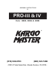
PRO-III & IV v _4.
PRO-III & IV ALL MODELS FOR TRUCKS WITHOUT SHELLS GO OP 10 K B H L C G E K N M N 4 K OP GO 1 GO OP A Q 1/2", 9/16", & 3/4" ©2011 KARGO MASTER-Pro3&4 _4.
A (4 ea.) 1/2" x 3 1/2" Hex Bolt B (2 ea.) 1/2" x 2 1/4" Button Head Bolt S (6 ea.) T (2 ea.) 1/2" x 13 x 2 1/2" Button Head Bolt 3/8" x 16 x 2 1/2" Button Head Bolt (yellow zinc plated, grade 5) C (2 ea.) 3/8" x 2 1/4" Button Head (yellow zinc plated, grade 5) D (8 ea.) 3/8" x 1 3/4" Button Head E (2 ea.) 5/16" x 2 1/4" Button Head Bolt F (8 ea.) G (4 ea.) 5/16" x 3/4" Button Head Bolt 5/16" x 3/4" Carriage Bolt P (4 ea.) 5/16" x 3/8" Allen Head Set Screw Q (2 ea.) 3/8” T Nut R (6 ea.
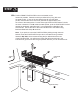
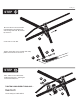
Pro3&4_4.1 STEP 1 #1= Position FRONT FOOTPLATES on the truck bedrail, as far forward as possible. Determine which pre-drilled hole (if any) falls over the stake pocket. If none of the pre-drilled holes fall over the stake pocket, mark and drill a hole in the foot plate that is approximately over the center of the stake pocket. Put bolt T through FOOTPLATE and start T Nut Q as shown.
Pro3&4_4.1 STEP 2 #1= Position the REAR FOOTPLATES against the bedrail. Secure the rear of the front FOOTPLATE to the bedrail usingBolt S and Bed Rail Clamp R as shown. Note: If you prefer to mount the FOOTPLATES by drilling 3/8" holes through the truck bedrail, locate the FOOTPLATES as per above, and attach using included fasteners D, K, & M. We recommend using the pre-drilled hole at the rear of the FOOTPLATES.
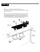
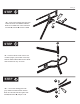
Pro3&4_4.1 Swaged joint & holes GO OP GO OP GOOP APPLICATION Apply a healthy air tight bead of goop around every swaged joint as shown, to prevent moisture from leaking into and out of the joint. If this is not done properly, the inside surface of the tubes can rust and rusty water can leak out. Maintain this joint seal throughout the life of your rack. Smooth goop at swaged joint & holes STEP 3 GO #1 = Cover entire swedge joints with goop sealant and join FRONT and REAR side channels together.
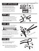
Pro3&4_4.1 G O O P STEP 6 #1 = Cover entire swedge joints with goop sealant and insert the CENTER CROSS BAR into the SIDE RAIL CUPS and attach with bolts E, washers K and lock nuts N. K E STEP 7 #1 = Insert PLASTIC CAPS onto the rear crossbar uprights, (the tall side of the tube). Slide the REAR CROSS BAR into the REAR LEG POSTS at the top, as shown.
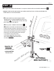
Pro3&4_4.1 STEP 9 #1 = Lift rake onto truck and make final adjustments and attach front and rear legs with bolts A, washers H, and nut L. P Center rack on truck bed. H Tighten up the bolts on the crossbar and clamp plates as well as the set screws P. L A H STEP 10 #1 = Attach the front SUPPORT UPRIGHT where the 1” tube begins to bend downward, then... N K TIGHTEN DOWN EVERYTHING AND....
Pro3&4_4.1 STEP 11 #1= Tighten down ALL NUTS AND BOLTS, except LEG FOOTPLATES and CENTER CROSS BAR C . DO NOT OVER TIGHTEN ON DOUBLE WALL BED CONSTRUCTION, AS THIS MAY DEFORM THE SHEET METAL OF THE PICKUP BED! #2= Center RACK over bed and tighten FRONT MOUNT BOLTS. On REAR MOUNT BOLTS be sure LOCK PINS J slide IN & OUT smoothly and freely before tightening the rear BOLTS. #3= Snug bolts in CENTER CROSS BAR C . #4= Modern truck beds are made from thin steel with limited load bearing capacity.
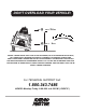
DON'T OVERLOAD YOUR VEHICLE! LBS. @ 100" = 3 X lbs. TURN FOR R E CE OV LBS. @ 35" = X lbs. WEIGHT CARRIED ABOVE THE FLOOR OF THE TRUCK BED (E.G. ON AN OVERHEAD TRUCK RACK) WILL SIGNIFICANTLY INCREASE THE VEHICLE'S TENDENCY TO OVERTURN. ALWAYS KEEP HEAVY LOADS EVENLY DISTRIBUTED AND AS LOW AS POSSIBLE. IT IS IMPORTANT TO NOTE THAT THE KARGO MASTER RACK LOAD BEARING CAPACITY OF 1700 LBS.