INSTRUCTION MANUAL POWER STAND UP WHEELCHAIR KARMAN HEALTHCARE INC. City of industry, CA 91748 www.KarmanHealthcare.com **Karman Healthcare Inc.
Table of Contents P.3 XO-202: Parts Explanation Chapter 1. SAFETY TIPS 1-1. Standing 1.2. Important symbols found on the vehicle 1-3. Safety information on driving and freewheel mode 1-4. Rear wheels 1-5. Armrests 1-6. Power drive attachments 1-7. Modifications Chapter 2. UNPACKING AND PREPARING THE STAND UP WHEELCHAIR XO-202 STAND UP WHEELCHAIR FOR USE 2-1. The original package and accessories. 2-2. Unfolding the stand up wheelchair Chapter 3. ADJUSTMENT 3-1. Adjusting the seat depth 3-2.
XO-202 Series 07 01 02 08 03 09 04 10 11 05 12 06 01 Backrest 07 Armrest 02 Chest belt 08 Controller Chest belt 03 Side Panel 09 Seat Rest 04 Rear Wheel 10 Knee Support Set 05 Motor/Differential Gear 11 Footrest 06 Front Wheel 12 Stand Up Casters 2
Chapter 1. SAFETY TIPS Powered Chair Electromagnetic Interference (EMI) WARNINGS The following warning listed below should reduce the chance of unintended brake release or powerchair movement, which could result in serious injury. 1. Do not operate hand-held transceivers (transmitter-receivers), such as citizens band (CB) radios, or turn ON personal communication devices, such as cellular phones, while the Powerchair is turned ON. 2.
1-2.
● Note that the wheelchair may brake or accelerate if you change the Driving Mode while the wheelchair is in motion! 1-4. Rear Wheels CURBS, INCLINES AND RAMPS Always practice with your healthcare professional or attendant before attempting to negotiate curbs, inclines or ramps alone. It is important for you to develop a safe technique that is suitable to your abilities. WARNING: Doing a “wheelie” (tilting the wheelchair backward to its balance point) can be dangerous.
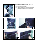
2-2. Unfolding the Stand up Wheelchair Please Proceed as Follows: • • Remove any transport straps or transport guards. Grasp the wheelchair at the backrest and pull backward and then push downward up to stop. (Fig. 1 & 2) • • • Tighten the knob on the left and right. (Fig. 3) Press the flip-back armrest forward. Connect the DC power line to power socket of battery. 1 2 3 Chapter 3.
3-2. Adjusting the Backrest Height (Fig-9 ~12) (1) Remove the backrest padding. (2) After removing the screws, the backrest height can be adjusted using the Allen wrench at 2 cm. intervals. (3) Retighten the screws.
3-3. Adjusting the Footrest Height The height of the footrest is adjustable and should be adjusted to compliment your body proportions to guarantee the best and most comfortable standing position possible. Footrest adjustment should also take account of your choice of seat cushion. (Fig-13 ~ 16) 13 14 16 15 • • After loosening the screws the footrest height can be adjusted using the different holes at 1.8cm. intervals. Retighten the screws.(not too tight) 3-4.
3-5. The Knee Support, Safety Belt and Chest Belt The most important safety features of the stand-up wheelchairs are the knee support, safety belt and chest belt. It is absolutely essential that these be correctly fastened around the user before attempting to stand up. 3-5-1. The knee support The knee support holds the knees in an extended posture and prevents the user from slipping out of the power wheelchair when standing up.
23 24 25 3-6. Adjusting the Armrest Height (1) Release the left and right screws up to the clamp, they can be removed to suit desired position.(Height 7”~10”) (Fig-26 & 27) (2) Retighten the screws of the clamp. 26 3-7. The Heels Strap (Fig-28) 27 28 The purpose of the heel strap is to prevent the legs and feet from slipping backwards. It is fitted behind the heels or higher.
Chapter4. DRIVING 4-1 Before Driving for the First Time Before you take your first trip, you should familiarize yourself well with the operation of the vehicle and with all operating elements. Take your time to test all functions and driving modes. Attention: • • You are within easy reach of all operating controls. The battery charge is sufficient for the distance intended to be covered. 4-2 Taking Obstacles Your electric wheelchair is able to overcome obstacles and curbs to a maximum height of 4cm.
4-4 Free Wheeling: Because the motors are designed to engage the electromagnetic brakes when the vehicle is not in use or when the power is OFF. There is also a manual feature that allows them to “free-wheel”. Free- wheeling is accomplished by pulling the free- wheeling levers to the free-wheeling position. (Fig29) 29 WARNING: • Never free-wheel your power wheelchair on a slope. • Never free-wheel the motors while operating your vehicle.
32 33 4. Pull upward(push forward on the joystick) and the wheelchair will go into stand up position. 5. Push downward(pull backward on the joystick) and the wheelchair will return to sitting position. Caution: • • Make sure your hand is not under the stand up mechanism. Make sure there are no children behind or near the wheelchair. Chapter 6. CONTROL SYSTEM 6-1. The SHARK II Remote Introducing SHARK SHARK heralds the dawn of new thinking in lower cost power chair control solutions.
Using the Seat Function Button (REMD11 & REMD21 Only) 1. Two seat functions are available for individual adjustment and are accessed via the Seat Function Button, (pictured at left). Seat Function 1 is “Stand-up Mode” and Seat Function 2 is normal “Seat Mode.” 2. Press the Seat button once to toggle the control unit from Drive mode to Seat mode. Seat Function 1 will be active as noted by the amber colored “1” LED. Seat Function 2 does not light up. 3.
Charging SHARK Plug the battery charger into the charging socket located at the front of the SHARK Control Unit. The SHARK Battery Gauge will indicate the system is being charged by cycling between a left-to-right chase and displaying the current battery state-of-charge. Driving is prevented (inhibited) while the system is being charged. Once the Battery Charger displays a ‘full’ battery charge, the battery charger plug may be removed.
6-2. Battery and Control Connection The main electrical control system is composed of motor, control box battery and controller. The connection of the control system is as follows. Stand up Motor 6-3. Charging Battery 1. First make sure that the battery charging line connects to the battery DC power socket and that the line is connected correctly. 2. Connect the AC power line to the AC socket.(110~220V) 3.
Chapter 7. MAINTENANCE • When cleaning your XO-202 series, use a dry or slightly moistened cloth to wipe the wheelchair down. For stubborn or oily stains, apply a mild detergent to the cloth. Do not hose down your XO-202 series with water. • Depending on the frequency of use, check tire pressure between once a week and once a month. If necessary, pump up the tires in line with manufacturer’s recommendations. • Check the state of the tread on the tires every one to six months.
FLASH CODES Flash codes indicate the nature of an abnormal condition directly from the SHARK Information Gauge. Without the use of any servicing tools, the condition can be simply diagnosed. Flash Code 1 Description User Fault 2 Battery Fault Possible stall timeout or user error. Release the joystick to neutral and try again. Try charging the batteries. Batteries may require replacing.
*****WARNING***** This chair is not intended for those who have: -Lower limbs joint contracture (absolute contra-indication) -Total hip replacement (THR) and total knee replacement (TKR) -Instability on lower extremity joints -Severe osteoporosis on lower extremities -Severe abnormal reflex (lower extremities withdraw reflex) -Severe postural hypotension -Low-shearing seat will be suggested to those who use positioning system 19
WARRANTIES Frame 3 Years Electrical 1 Year Parts Motor/Transaxle/Brake 6 Months 1 Year 1. Structural frame components including platform, fork, seat post and frame welds are warranted, to the original owner/ 2. To present a claim, Customer shall deliver the defective part for exchange or repair if possible to an Authorized Karman provider. 3. This warranty is for the replacement or repair, at the option of Karman Healthcare Inc.