Owners Manual VFX Series Decorative Aerators Contents Important Safety Instructions. . . . General Owner’s Instructions. . . . Unit Specs. . . . VX Pattern Sizes. . . . 2400VFX, 3400(H)VFX, 4400(H)VFX Parts Included. . . . 2400VFX, 3400(H)VFX, 4400(H)VFX Assembly. . . . 8400VFX, 2.3(H)VFX, 5.1VFX, 5.3(H)VFX Parts. . . . 8400VFX, 2.3(H)VFX, 5.1VFX, 5.3(H)VFX Assembly. . . . Mesh Screen Attachment. . . . VFX Installation Instructions. . . . Control Panel Installation. . . .
THANKS We at Kasco Marine, Inc. would like to both thank and congratulate you on your purchase of the VFX model aerator. We appreciate you choosing Kasco and for your purchase. Your decision to purchase Kasco’s VFX model Aerator will not disappoint you. The VFX model Aerator will be a great addition to your body of water. It will help improve the water quality by adding much needed oxygen and circulation. It will also enhance the aesthetics of the pond or lake with a beautiful pattern.
important to test the GFI breaker in the control panel upon each installation/reinstallation of the unit to ensure proper functioning. WARRANTY Kasco aerators are the result of over 35 years of design and engineering. Kasco products are built to withstand the toughest conditions. Kasco Marine backs each VFX model aerator with either a 2 Year or 3 Year Warranty depending on the model.
2400VFX, 3400(H)VFX, 4400(H)VFX Parts Included 1. Aerator (Unit w/cord or unit with Disconnect (1) 2. Float (with two 50’ mooring ropes attached) (1) 3. 1/4-20 x 3 1/4” Phillips Pan Head Screw (4) 4. 1/4” split washers (4) 5. 1/4” (3/4” outer diameter) Flat Washer (4) 6. 3/8”-16 x 1-3/4” Hex Head Bolt (2) 7. 3/8” Flat Washer (4) 8. Cushions for Legs (4) 9. Bottom Screen Section (3) 10. Bottom Screen Clips (2) 11. 3/8”-16 Nylon Lock Nut (2) 12. #8 nut (6) 13. #8 flat washer (12) 14. #8 lock washer (6) 15.
power cord guide Bolt holes #8 lock washer #8 screw 5. Use one of the 1/4”-20 x 3-1/4” Phillips Pan Head Screws (Part 3), one 1/4” split washer (Part 4), and a 1/4” Flat Washer (Part 5) to secure the float. Make sure the split washer goes between the bolt head and the flat washer. Insert screw with washers through bolt hole in float Tighten until snug with a Phillips Head screw driver and repeat for 3 remaining screws. 6.
10. Turn the assembly upright again. At this time, if the cord contains a metal strain relief, you can use the chain connector and attach it in one of the opening at the rope placement. The chain connector will easily fit if installed from the bottom or top side of the opening. It will not fit if installed from side of opening. Use the Nylon Cable Tie included to secure the power cord to a molded hole in the float to prevent cord damage if there is no strain relief on the cord.
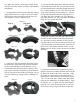
ual. Make sure you have all the parts needed. If any shortages are found, contact your Kasco representative immediately. 2. Arrange the three Float Sections (Part #B1) upright (plug on bottom) so the overlap of one section aligns with the next section and loosely push the three sections together to form a continuous ring. 8400, 2.3 Float Up (plug) 5.1, 5.3 8400, 2.3 8400, 2.3 Float Down 5.1, 5.3 3.
If installing a new Quick Disconnect, please refer to Quick Disconnect instructions. Also, at this time, lights can be installed if purchased. Step 6 1 chain strain relief 7. See “Mesh Screen Attachment” section before connecting the bottom screen to the float. Position the Bottom Screen (Part #B9) over the float so the motor housing (can) passes through the large hole in the center of the screen.
VFX Installation Instructions Before installing 3 phase units (2.3, 5.3) into the pond, please refer to 3 phase startup procedure. 2. Insert existing stainless steel screen centered inside mesh cone with approximately 2 inches of mesh overlap to the top ring of the screen. Attach mesh to the top ring of the screen in (3) equally spaced locations using cable ties. Use the ropes to position the aerator in the desired location in the pond/lake.
Control Panel Installation STEP ONE Inspect the panel for any damage and any components that may have loosened during shipping. Control panel must be installed a minimum of 5ft (3m in Canada) from the inside wall of the pond, unless separated from the body of water by a fence wall, or other permanent barrier that will make the unit inaccessible to persons in the water. Install the control panel to a post structure, side of a building, or other reliable means.
White connects to Terminal Green connects to Terminal #7 G STEP FOUR: Test the GFCB with the test button now and every 30 days. If lights are installed, they can now be installed per Instructions included with the lights. Once completed, power can be restored to the panel.
C85 / C95 non-metallic Wiring Diagram * C95 uses 30 Amp breaker 12
3 Phase Startup Procedure If a Kasco Control Panel is not provided, please refer to the following warnings: When inherent overheating protection is not provided: use with approved motor control that matches motor input in full load amperes with overload element(s) selected or adjusted in accordance with control instructions. Utiliser un démarreur approuvé convenant au courant à pleine charge du moteur et dont les éléments thermiques sont réglés ou choisis conformément aux instructions qui l’accompagnent.
C85 / C95 non-metallic and 3 Phase Control Panel Timer TIME CLOCK SETTING To set the current time, turn the inner dial clockwise. Do not set the time by rotating “outer” dial. Turn the minute hand or small plastic inner dial clockwise until the time of day on the outer dial is aligned with the triangle marker on the inner dial (two o’clock position). Example for 10:00 AM. Turn the minute hand clockwise until 10:00 AM is aligned with the triangle on the inner dial.
2400VFX, 3400VFX, 3400HVFX, 4400VFX, 4400HVFX REPLACEMENT PARTS 2400, 3400, 4400 Parts Diagram 12 13 6 5 11 10 1 18 8 7 ITEM NO. PART NO. DESCRIPTION Replacement Parts/QTY.
ITEM NO. 1 2 3 4 5 6 7 8 9 10 11 14 15 11 9 14 8 4 10 PART 8400 DESCRIPTION NO. /QTY. 990275 O RING, CORD 1 990280 SEALING PLUG 1 O RING 1 990281 ZINC ASSEMBLY 1 840475 140312 RETAINING CLIP 6 LOCK WASHER, 1/4" 6 840537 584692 1/4-20 X 1-3/8" BOLT 6 WASHER, 1/2" 1 475642 821100 TOP DISK, 8400VFX 1 821120 8400VFX TUBE 1 1/2-20 HEX NUT, LEFT HAND 821095 1 THREADED 821114 PROP ASSEMBLY, 3.1A/8400VFX, 1 BRONZE, INTERNAL 1 241024 WASHER, 1/2IN, TOOTH LOCK 15 2 3 5 6 7 8400VFX, 2.
990290 990280 990281 840475 140312 840537 584692 475642 821124 821095 510250 510200 PART NO. DESCRIPTION 8 ITEM NO. 1 2 3 4 5 6 7 8 9 10 11 12 9 O RING SEALING PLUG O RING ZINC ASSEMBLY RETAINING CLIP LOCK WASHER, 1/4" 1/4-20 X 1-3/8" BOLT WASHER, 1/2" PROP ASSEMBLY, 5.1A/5.1VFX, 1/2-20 HEX NUT, LEFT HAND THREADED 5.1VFX TUBE TOP DISK, 5.1VFX WASHER, 1/2IN, BRONZE, INTERNAL TOOTH LOCK 12 241024 13 13 10 1 1 1 1 6 6 6 1 1 1 1 1 1 5.1VFX PARTS LIST/QTY. 4 11 6 5.1VFX, 5.
Maintenance Recommendations ** Under No Circumstances should anyone enter the water while a aerator is operating. ** ** Please keep the original box for maintenance shipping. ** The following maintenance procedures can be utilized to ensure many years of quality performance from your Kasco aerator and reduce the need for more costly repair work. PROPER INSTALLATION: Proper installation of Kasco equipment will include a power source with ground fault interruption (GFI).
void the warranty. This includes tampering with the unit, power cord, and/or control box. Please contact Kasco Marine, Inc. at 715-262-4488 for your nearest Authorized Repair Center. Warranty Policy Warranty Period: Models: 2400VFX, 3400(H)VFX, 4400(H)VFX - 2 years Models: 8400VFX, 2.3(H)VFX, 5.1VFX, 5.3(H)VFX - 3 years Kasco® Marine, Inc. warrants this aerator to be free from defects in material or workmanship (except for the ropes, power cord, and propeller) under normal use and service.
zation Number and/or Repair Form so we know the repair is coming. Kasco Marine does estimates on repairs at the request of the customer. The request for estimate should be included in the letter that accompanies the returned unit and must include a daytime phone number and/or e-mail address. Estimate options are as follows: We will contact the customer with a total after the unit has been evaluated, but before the work is performed.
be fine. Contact a Kasco representative before restarting the unit. “My Aerator flow seems to fluctuate and/or be less than usual.” This can occur because of a few different reasons. Most of the time, this symptom is caused from unit being clogged with debris. A mat of weeds, many leaves, plastic bags, etc. can clog up the unit and cause it to be starved of water. If the unit does not have the proper amount of water, the flow or pattern will fluctuate up and down and look sporadic.
800 Deere Rd. Prescott, WI 54021 Phone: 715-262-4488 - Fax: 715-262-4487 www.KascoMarine.com Sales@KascoMarine.com Customer Repair Form * Important Reminders * • All repairs sent in MUST be accompanied by a copy of this completed sheet! • Routine maintenance consists of checking the zinc anode regularly and replacing if necessary, keeping the unit clean, keeping the stainless steel can clean, and having the seals and oil replaced every 3 years depending on use.
Registration Information Please register your aerator online at: www.kascomarine.com Also fill in the information below and keep for your records. Model # (Ex. 5.1VX)_______________________________ Serial # (Ex. 8001VX511725)______________________________ Purchase Date:_____________________ Purchased From:___________________________________ Registration Date: ___________________________ Kasco Marine, Inc. 800 Deere Rd. Prescott, WI 54021 Phone (715) 262-4488 • Fax (715) 262-4487 www.kascomarine.