MOVING WATER FORWARD, SINCE 1968 AERATOR & CIRCULATOR 2400, 3400, 3400H, 4400, 4400H Operation & Maintenance Manual 3020379 ANSI/UL 778: 2016 Ed.6+R:22Feb2017 CSA C22.2 #108: 2014 Ed.5 Document number 884740 Document version 2021.1.1 800 Deere Rd. Prescott, WI 54021 | 715.262.4488 | sales@kascomarine.com |& kascomarine.
TABLE OF CONTENTS Safety First �������������������������������������������������������������������������������������������������������������������������������2 Unit Specifications ������������������������������������������������������������������������������������������������������������������3 General Instructions ���������������������������������������������������������������������������������������������������������������3 Parts Included (Aerator) ���������������������������������������������������������
Back to Contents SAFETY FIRST IMPORTANT: PLEASE READ THIS MANUAL AND SAVE FOR FUTURE REFERENCE WARNINGS: Moving Machinery Shock Hazard Please read and follow these extremely important safety and handling instructions for your Kasco equipment. Following these instructions will help ensure your safety and the quality performance of your equipment. • Under NO circumstances should anyone enter the water with the electrical equipment plugged in and/ or in operation.
Back to Contents UNIT SPECIFICATIONS Model Voltage Operating Amps Locked Rotor Amps Single-phase Aerators and Circulators 2400A/C 110-120 5.0 12 3400A/C 110-120 6.7 18 3400HA/HC 208-240 3.4 9 4400A/C 110-120 11.3 40 4400HA/HC 208-240 5.7 20 GENERAL INSTRUCTIONS Inspect the Shipment Immediately inspect your shipment for any visible damages. Any damage should be reported immediately to your carrier and Kasco.
Back to Contents PARTS INCLUDED (AERATOR) Item Description Qty Part No.
Back to Contents ASSEMBLY INSTRUCTIONS (AERATOR) 1. Rest the float (D) on the cage, aligning the power cord to the notch in the float. Align power cord with this notch D 2. Locate the bolt holes marked with the indicators. Indicator mark 3. Secure the float to the cage with the 1/4"-20 x 3-1/2" screws (A), 1/4" split lock washers (B), 3/4" OD flat washers (C), and float retaining clips (E), as shown below. 4. Repeat for all three bolt holes.
Back to Contents ASSEMBLY INSTRUCTIONS (AERATOR, CONT.) If you are not installing a mesh screen with your bottom screen, continue to step 10. If you are not installing a bottom screen, continue to step 12. 5. Wrap the flat mesh into a cone shape by overlapping both vertical edges by approximately 1 inch and aligning the top and bottom edges of mesh. 6. Use three cable ties evenly spaced along the vertical seam to secure the mesh at the top, middle, and bottom. 7.
Back to Contents ASSEMBLY INSTRUCTIONS (AERATOR, CONT.) 10. Turn the unit upside down and position the bottom screen (H) flush with the float. 11. Fasten the bottom screen to the float using the 3/8"-16 x 2-1/2" screws (F), 3/8" flat washers (G), bottom screen clips (I), and 3/8"-16 nuts (J). 11 J G I Position the clip flanges on either side G of a vertical bar F 12. Loop the mooring lines through either two or three evenly spaced holes on the float. 13.
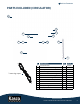
Back to Contents PARTS INCLUDED (CIRCULATOR) A D E B G F H I I J K C L 3 mooring ropes ID Description Qty Part # A Horizontal Float 1 213002 B Horizontal Float mounting bracket 2 993220 C Can strap 1 997174 D Tie-down ring 1 993230 E 1/4”-20 x 1/2” serrated flange screw 5 774037 F 3/8”-16 x 1” serrated flange screw 1 840533 G 3/8”-16 serrated flange nut 1 840532 H 3/8”-16 x 1” hex head cap screw 1 566250 I 3/8” flat washer 2 462216 J 3/8”-16 nut 1 462214
Back to Contents ASSEMBLY INSTRUCTIONS (CIRCULATOR) 1. Slide the can strap (C) onto the unit with the flanges directly opposite the cage clamp. The strap should be about 1.5 inches from the cage. 2. Secure the flanges together by fitting a 3/8”-16 x 1” hex head cap screw (H), two 3/8” flat washers (I), and a 3/8”-16 nut (J) in the hole closest to the can. 3. Fit the bottom hole of each mounting bracket (B) over the hardware now securing the can strap flanges. 1 Cage clamp C 1.
Back to Contents ASSEMBLY INSTRUCTIONS (CIRCULATOR, CONT.) 4. Angle the unit as desired by aligning one of the three the holes in the flanges with the corresponding holes in the brackets. Secure the can strap to the brackets with the 3/8”-16 x 1” serrated flange screw (F) and 3/8”-16 serrated flange nut (G) to fix the unit in one of the angles below. G F Upward angle: Align the bracket and flange holes furthest from the cage to angle the unit toward the float in the water (below).
Back to Contents ASSEMBLY INSTRUCTIONS (CIRCULATOR, CONT.) 6. Secure the tie-down ring (D) to the float using another 1/4”-20 x 1/2” serrated flange screw (E). 7. Attach snap clips (L) to both ends of both chains (K). 8. Use the snap clips to attach the chains to the cage as shown below, evenly spaced on either side of the cage clamp. E 6 D 8 Cage clamp L K 7 L 9. Tie mooring ropes to both chains and to the tie-down ring to provide three anchor points for the unit and float (A) as shown below. 10.
Back to Contents INSTALLATION INSTRUCTIONS Use ropes to position the aerator or circulator in the desired location in the pond or lake. Anchor the ropes or secure them to the shoreline so that they are free of slack, but not tight. To prevent twisting of the unit due to motor torque, place the anchor at least 3 feet from the float for each foot of depth. (Example: a 6-foot-deep pond would require an anchor 18 feet horizontally from the float.
Back to Contents MAINTENANCE RECOMMENDATIONS UNDER NO CIRCUMSTANCES should anyone enter the water while equipment is operating. The following maintenance procedures can ensure many years of quality performance from your Kasco aerator or circulator and reduce the need for more costly repair work. Proper Installation Proper installation of Kasco equipment will include a power source with Ground Fault Interruption (GFI).
Back to Contents MAINTENANCE RECOMMENDATIONS (CONT.) Seal And Oil Replacement This is a sealed motor assembly, and seals will wear out over time (similar to brake pads on a car). Replacing the seals and changing the oil after three years may add longevity to the operation of the motor, saving you the cost of more expensive repairs.
Back to Contents TROUBLESHOOTING TIPS (CONT.) “My aerator or circulator hums, but will not start. When I spin the prop with a stick, it starts up.” (for single phase units only) This indicates a problem with the starting capacitor. Each Kasco aerator/circulator is equipped with a starting capacitor to get the unit going when it is first plugged in.
Back to Contents UNIT REPLACEMENT PARTS ID Description Qty Part # A 2400 model propeller 1 240170 A 3400 model propeller 1 340125K A 4400 model propeller 1 440430 B Sacrificial anode assembly (1/2” shaft) 1 243475 B Sacrificial anode assembly (5/8” shaft) 1 840475 C Cage 1 990200 D 3/8”-16 x 1-1/4” serrated flange screw 1 840543 E 3/8”-16 serrated flange nut 1 840532 A B C D E Sealed motor unit 1/2HP-1HP AERATOR & CIRCULATOR MANUAL 16
Back to Contents WARRANTY Warranty Period: Models 2400A/C, 3400A/C, 3400HA/HC, 4400A/C, 4400HA/HC = 2 years Kasco® Marine, Inc. warrants this aerator/circulator to be free from defects in material or workmanship (except for the ropes, power cord, and propeller) under normal use and service. The Kasco Marine, Inc. obligation under this warranty is limited to replacing or repairing free of charge any defective part within the warranty period.
Back to Contents Kasco only accepts complete assemblies for warranty repair. We must receive the power cord and all other components with the motor as originally assembled. Kasco will bill the customer to replace any missing parts necessary for repair. It is not necessary to return the control panel, mount, or other parts with the motor assembly, unless specifically requested by a Kasco representative. Please attach a repair form with the shipment.
Back to Contents REPAIR CONTACT FORM • Kasco requires that all equipment sent for repair MUST be accompanied by this form and marked to Repairs attention. • Unit should be cleaned before shipping. • Kasco is NOT responsible for shipping damage accrued in return shipment. • It is the responsibility of the customer to ship and pay freight to Kasco.