Owners Manual Aerator & Circulators Contents Important Safety Instructions. . . . . . General Owner’s Instructions. . . . . . Unit Specs. . . . . . 2400AF, 3400AF/HAF, 4400AF/HAF Parts. . . . . . 2400AF, 3400AF/HAF, 4400AF/HAF Assembly. . . . . . 8400AF, 2.3AF, 3.1AF, 3.3AF, 5.1AF, 5.3AF Parts. . . . . . 8400AF, 2.3AF, 3.1AF, 3.3AF, 5.1AF, 5.3AF Assembly. . . . . . Mesh Screen Attachment. . . . . . Installation Instructions. . . . . . Circulator Parts (CF Models). . . . . .
Thanks! We at Kasco Marine, Inc. would like to both thank and congratulate you on your purchase of the Pond Aerator or Water Circulator model. We appreciate you choosing Kasco and for your purchase. Your decision to purchase Kasco’s Pond Aerator or Water Circulator will not disappoint you. The Pond Aerator or Water Circulator will be a great addition to your body of water. It will help improve the water quality by adding much needed oxygen and circulation.
2 Year Warranty or 3 Year Warranty depending on the model. This warranty covers any and all manufacturers defects within the warranty period from the date of purchase (See Warranty, Warranty Claim, & Return Policy). Please register your Aerator online at: www.kascomarine.com (under the technical tab) USE AND OPERATION Kasco Aerators are designed and engineered for continuous duty, such as on fish farms or other aquaculture applications, or on-demand use, as needed in a recreational water feature.
3 • 4 • • tional C-25 (3) or C-85 (4) 9/16” Socket and Ratchet (for optional bottom screen) 9/16” Wrench (for optional bottom screen) Nylon Tie for cord 5 7 8 2 1 2400AF, 3400AF/HAF, 4400AF/HAF Assembly STEP ONE Make sure you have all the parts needed. If any shortages are found, contact your Kasco representative immediately. STEP TWO Set motor housing upright (stainless steel can down) on a flat surface.
the flat washer. Insert screw with washer through bolt hole in float Use one float retaining clip (Part 6) under the top ring of the cage. There is a U-shaped indent in the clip that will fit snug against the top ring of the cage. The 1/4”20 x 3-1/2” will then thread into the retaining clip.
this time, go to Light kit instructions. • • Adjustable crescent wrench Nylon Tie for cord 8400AF, 2.3AF 8400AF, 2.3AF, 3.1AF, 3.3AF, 5.1AF, 5.3AF Parts POND AERATOR PARTS INCLUDED Aerator Unit with cord (Cord may be shipped separately) (1) B. Large Float Ring (8400AF, 2.3AF) 1. Float Sections (3) 2. Top Float Bracket (3) 3. Bottom Float Bracket w/Rope (3) 4. 9” x 3/8” Bolt (6) 5. 3/8” Lock Nut (6) 6. Unit Mounting Bracket (3) 7. 1/4” x 3/4” Bolt (6) 8. 1/4” Lock Washer (6) 9.
STEP TWO Arrange the three Float Sections (Part #B1) upright (plug on bottom) so the overlap of one section aligns with the next section and loosely push the three sections together to form a continuous ring. 8400AF, 2.3AF which should now be extending through the assembly. Loosely install the six 3/8” Lock Nuts (Part #B5) on the ends of the bolts (do not tighten yet).
STEP SIX (8400,2.3) Lift Float Assembly and place over Aerator Assembly. Adjust one unit Mounting Bracket at a time and nest the cage ring in the lower notch of the Unit Mounting Bracket for the 3.1, and 5.1 units. Nest the cage ring in the middle notch of the Unit Mounting Bracket for the 8400. 8400, 2.3 Once all three Unit Mounting Brackets are seated correctly on the cage ring, add remaining 1/4” x 3/4” Bolts and 1/4” Lock Washers to lower mounting hole.
Mesh Screen Attachment 1. Take flat mesh pattern and wrap into cone shape by overlapping both vertical edges by approximately 1 inch and aligning top and bottom edges of mesh. Secure mesh vertical seam at the top, bottom and middle using (3) cable ties. Attach 3 cable ties to top ring equally spaced Overlap vertical edges 2 inch overlap Attach 3 cable ties 3. Flip mesh and screen assembly over and use remaining cable ties to secure mesh to small bottom diameter of the stainless steel ring.
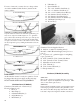
For ease of removal, you may choose to keep at least one anchor within reach from shore, just below the water’s surface. Correct Anchoring Incorrect Anchoring 6. U-Bracket (2) 7. Spacer Bracket (2) 8. 1/4” x 1/2” Stainless Steel Bolt (8) 9. 1/4” x 1” Stainless Steel Bolt (3) 10. 1/4” x 1-1/4” Stainless Steel Bolt (2) 11. 1/4” Stainless Steel Lock Nut (8) 12. 1/4” Stainless Steel Hex Nut (2) 13. 1/4” Stainless Steel Lock Washer (5) 14. 50’ Black Nylon Ropes (2) 15.
STEP THREE Position the Adjustment Bracket (Part B3) over the two holes at the back end of the Float and Base Strap. Loosely secure the Adjustment Bracket to the Float using two 1/4” x 1/2” (Part B8) Stainless Steel Bolts and two Stainless Steel Lock Washers (Part B13). (See photo above for orientation.) STEP SIX Place the two U-Brackets (Part B6) directly across from each other (180O) over the top ring of the motor cage.
2400 & 3400 4400 & 8400 STEP NINE Wrap the Draw Band (Part B5) around the motor housing and position so that the back of the Draw Band touches the marks drawn in Step Five. There is no front or back to the Draw Band itself - it is reversible. Orient the arm of the Draw Band so it aligns with the cord clamp on the cage of the motor housing and is parallel to the Angle Brackets attached in Step Eight. Secure using a 1/4” x 1” Stainless Steel Bolt and a 1/4” Lock Nut.
building, or other reliable means. This structure must support the panel and prevent movement/flexing of the panel. Use #10 x 1” or longer screws in the mounting points of the control panel to secure to the post structure. NOTE: The control panel must be hung upright in order to be waterproof. It is also advised to mount the panel out of direct sunlight if possible. Mounting the panel in a North direction will prevent heat buildup inside the panel.
Record the following data while the Aerator is operating in the water under load: DOES POP OUT, OR IF THE G.F.C.I. FAILS TO RESET PROPERLY, DO NOT USE TIMER! CONTACT A QUALIFIED SERVICE TECHNICIAN! Voltage: L1-L2 ________ UNDER NO CIRCUMSTANCES SHOULD ANYONE ENTER THE WATER WHEN A UNIT IS IN OPERATION! L1-N _________ L2-N _________ Amperage: L1 __________ L2 __________ TIMER-OPERATION INSTRUCTIONS C-25 Control Box will turn the aerator ON & OFF with the TIMER.
C85 / C95 non-metallic Wiring Diagram * C95 uses 30 Amp breaker 15
3 Phase Startup Procedure 2. If a Kasco Control Panel is not provided, please refer to the following warnings: 3. When inherent overheating protection is not provided: use with approved motor control that matches motor input in full load amperes with overload element(s) selected or adjusted in accordance with control instructions.
C85 / C95 non-metallic and 3 Phase Control Panel Timer TIME CLOCK SETTING To set the current time, turn the inner dial clockwise. Do not set the time by rotating “outer” dial. Turn the minute hand or small plastic inner dial clockwise until the time of day on the outer dial is aligned with the triangle marker on the inner dial (two o’clock position). Example for 10:00 AM. Turn the minute hand clockwise until 10:00 AM is aligned with the triangle on the inner dial.
ITEM NO. 1A 2 3 4A 4B 5A 5B 5C 5D 6 7 8 9 PART NO. 990275 990280 990281 243475 840475 240170 340125 440400 820450 261234 261240 990201 261231 5 1 2 3 DESCRIPTION CORD O RING SEALING PLUG SEALING ORING ZINC ASSEMBLY (2400 & 3400 MODELS) ZINC ASSEMBLY (4400 & 8400 MODELS) 2400 K PROP (2400 MODEL) 3400 J PROP (3400 MODEL) 4400 M PROP (4400 MODEL) 8400 Y PROP (8400 MODEL) HEX NUT 5/16-18 X 1 HHCS CAGE FLAT WASHER 4 QTY. 1 1 1 1 1 1 1 1 1 1 1 1 2 7 6 2400, 3400, 4400, 8400, 2.
ITEM NO. 1A 1B 2 3 4 5 6A 6B 7 8 9 10 1 2 3 4 5 PART NO. DESCRIPTION 3.1AF/QTY. 821114 PROP ASSEMBLY, 3.1A/8400VFX, 1 821124 PROP ASSEMBLY, 5.1A 1 WASHER, 1/2" 1 475642 ZINC ASSEMBLY 1 840475 SEALING PLUG 1 990280 O RING 1 990281 990275 O RING, CORD 1 990290 O RING, CORD (5.1) 1 RETAINING CLIP 6 140312 LOCK WASHER, 1/4" 6 840537 6 840539 1/4-20 x 3/4" HEX HEAD CAPSCREW RING, AERATOR MOUNTING 1 993300 10 6 8 9 3.1, 3.3, 5.1, 5.
Maintenance Recommendations Under No Circumstances should anyone enter the water while a unit is operating. Turn Off and Disconnect electrical power prior to any Maintenance or Servicing Ground fault interrupters are a safety feature that can also alert you to electrical leaks in the equipment. It is extremely important to test the GFI upon installation, each reinstallation, and monthly thereafter to ensure proper operation.
• • • • ers Manual. The Aerator is returned for repair without the power cord or if the unit, control box, or power cord are altered in any way from original shipment. Cuts in the power cord are not covered under warranty. The Aerator is not used with the supplied GFI control box. The Aerator is damaged by unauthorized tampering. The Sacrificial Zinc Anode around the propeller shaft shows significant deterioration. (The Anode must be inspected periodically and replaced if necessary.
you contact Kasco to narrow down the problem. • How long does it take to trip the breaker? • Does it always take the same amount of time to trip? • How many times has it tripped? • Has there been any electrical problems in the area recently? “My Aerator seems to run slowly.” This can also be a symptom of several possible problems. There could be an electrical problem where the unit is not getting the proper voltage.
800 Deere Rd. Prescott, WI 54021 Phone: 715-262-4488 - Fax: 715-262-4487 www.KascoMarine.com Sales@KascoMarine.com Customer Repair Form * Important Reminders * • All repairs sent in MUST be accompanied by a copy of this completed sheet! • Routine maintenance consists of checking the zinc anode regularly and replacing if necessary, keeping the unit clean, keeping the stainless steel can clean, and having the seals and oil replaced every 3 years depending on use.
Registration Information Please register your aerator online at: www.kascomarine.com Also fill in the information below and keep for your records. Model # (Ex. 3.1AF)_______________________________ Serial # (Ex. 8001A311725)______________________________ Purchase Date:_____________________ Purchased From:___________________________________ Registration Date: ___________________________ Kasco Marine, Inc. 800 Deere Rd. Prescott, WI 54021 Phone (715) 262-4488 * Fax (715) 262-4487 www.kascomarine.