
Product Manual

11
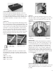
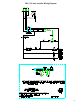
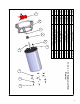
STEP THREE
Position the Adjustment Bracket (Part B3) over the two
holes at the back end of the Float and Base Strap. Loosely
secure the Adjustment Bracket to the Float using two 1/4” x
1/2” (Part B8) Stainless Steel Bolts and two Stainless Steel
Lock Washers (Part B13). (See photo above for orienta-
tion.)
STEP FOUR
Place one of the three Angle Brackets (Part B4)perpendicu-
lar to the Base Strap at the front end of the Base Strap. One
of the two center holes of the Angle Bracket should be posi-
tioned over the hole in the Base Strap and the threaded hole
in the Float. Secure the Angle Bracket to the Float using
three 1/4” x 1/2” Stainless Steel Bolts and three Stainless
Steel Lock Washers. (See photos in the next column for
specic instructions based on the size circulator purchased.)
Tighten all hardware at this time with the 7/16” (11mm)
socket and wrench.
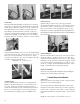
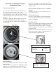
Models 2400
& 3400 - Angle
posterior to bolts.
Model 8400 & 4400
Angle anterior to bolts.
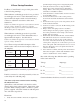
STEP FIVE
With a felt-tip marker, draw three to four marks around
the circumference of the motor housing at the appropriate
measurement from the back (or bottom) of the motor hous-
ing given:
2400: 3/4” (1.9cm)
3400: 3-3/8” (8.57cm)
4400: 5-1/2” (14 cm)
8400: 7-1/2” (19 cm)
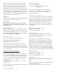
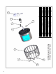
STEP SIX
Place the two U-Brackets (Part B6) directly across from
each other (180
O
) over the top ring of the motor cage. The
cord clamp on the cage should be 90
O
from each of the
U-Brackets
.
1/4” x 1”
Bolt and
Locking
Nut
Power Cord1/4” x 1-1/4”Bolt
and Nut
1/4” x 1”
Bolt and
Locking
Nut
1/4” x 1-1/4”Bolt
and Nut
STEP SEVEN
Insert the Spacer Bracket (Part B7)under the U-Bracket
and inside the cage. Secure this assembly using one 1/4”
x 1” Bolt (Part B9) and a 1/4” Lock Nut (Part B11), and
one 1/4” x 1-1/4” Bolt (Part B10) and a 1/4” Hex Nut
(Part B12). The longer bolt should be on the side of the
U-Bracket that is closer to the cord clamp. Tighten the
hardware using the 7/16” (11mm) wrench and socket &
wrench until the U-Bracket clamps rmly around the cage
(U-Bracket should pull together slightly). Repeat with the
second U-Bracket.
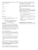
STEP EIGHT
Attach an Angle Bracket to each of the longer (1-1/4”) bolts
on the U-Brackets (See photo for orientation) with a 1/4”
Lock Nut.