Owners Manual J Series Fountains 5.1JF, 5.3JF, 7.3JF, 5.3HJF, 7.3HJF Kasco Marine, Inc. 800 Deere Rd. Prescott, WI 54021 PH (715) 262-4488 kascomarine.
Table of Contents Important Safety & Additional Notes pg 2-3 Tools and Supplies Needed, Unit Specs pg 3 Parts, Nozzles Included pg 4 – 5 Optional Premium Nozzles pg 6 Assembly Instructions pg 7 – 10 Nozzle Installation Instructions pg 11 Unit Installation Instructions pg 12 3-Phase Startup Procedure pg 13 Maintenance pg 14 Warranty pg 15 Repair pg 16 Troubleshooting Tips pg 17 – 18 Replacement Parts pg 19 – 20 Repair Contact Form pg 22 Important Safety: Please read and follow the
• • • • Extreme caution should be used around water, especially cold water, as in Spring, Fall, and Winter, which poses a hazard in and of itself. NEVER lift or drag the equipment by the power cords. If you need to pull the unit to the side of the pond, use the anchoring ropes. Do not use boats that tip easily for installation and follow all boating safety rules and regulations, including wearing a PFD (Personal Flotation Device).
Parts Included Unit Size 2hp 3hp 5hp 7hp Voltage/Phase G (PartNo) 208-240/1φ 8400JF 208/3φ 2.3JF 460/3φ 2.3HJF 208-240/1φ 3.1JF 208/3φ 3.3JF 460/3φ 3.3HJF 208-240/1φ 5.1JF 208/3φ 5.3JF 460/3φ 5.3HJF 208/3φ 7.3JF 460/3φ 7.
Nozzles Included Note: The Birch nozzle is preinstalled on the unit from the factory. *Pattern sizes listed are approximate. Variations in voltage caused by regional electrical differences or voltage drop due to long power cords may result in reduced pattern sizes.
Optional Premium Nozzles (not included) Premium nozzles are not included as standard but may be added and installed at any time. These nozzles offer unique patterns that truly showcase your pond or lake. Contact Kasco Marine at sales@kascomarine.com or your local distributor for order information. *Pattern sizes listed are approximate. Variations in voltage caused by regional electrical differences or voltage drop due to long power cords may result in reduced pattern sizes.
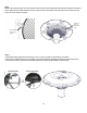
Assembly Instructions Step 1 Place the float (D) over the unit assembly (G). Ensure the three channels on the inside of the float line up with the threaded holes in the baseplate, and the Kasco logo on the top side of the float lines up with the power cord on the unit assembly. This will allow the power cord to run in the power cord channel on the underside of the float later.
Step 3 On the underside of the float, line up the (3) bottom screen clips (I) and start threading in the (3) 3/8 – 16 x 1/2’’ serrated hex head screws (J), but do not tighten down at this time. Be sure the clips can slide back and forth freely. Leave Gap Step 4 – See “Troubleshooting” on pg. 17 for extra help deciding which mesh screen should be installed Kasco recommends the 3/4’’ mesh screen (M) for all standard nozzles and the 1/4’’ mesh screen (L) for premium nozzles.
Step 6 (Optional) Flip mesh and screen assembly over and use (2) cable ties to secure mesh to small bottom diameter of the bottom screen. Clip off excess cable ties once tightened and mesh is secured. Step 7 Lift the unit and slide the bottom float screen (H) with the mesh over the can and up to the bottom of the float, allowing the unit power cord to exit between them in the dedicated channel.
Step 8 Slide the clips toward the center and over the bottom screen so that one of the vertical bars is between the two flanges on each clip as shown. Tighten all three serrated hex head screws to secure the screen to the bottom of the float, being sure not to pinch the power cord. 9/16’’ side of wrench tool required.
Nozzle Installation Instructions After removing the current nozzle and ensuring that the nozzle O-ring (F) is properly seated in its groove, twist the selected nozzle (E) clockwise (as viewed from the top) so that the flanges in the nozzle lock into place on the top of the pump chamber by hand. Twist until the nozzle flanges can move no further and are completely snug. Nozzles can be changed conveniently without removing the float or using any tools.
Unit Installation Instructions Note: Before installing 3-phase units (2.3JF, 3.3JF, 5.3JF, 7.3JF, 2.3HJF, 3.3HJF, 5.3HJF, 7.3HJF) into the pond, please refer to 3-phase startup procedure on page 13. Use ropes (N) to position the fountain in the desired location in the pond or lake. Anchor the ropes or secure them to the shoreline so that they are free of slack, but not tight. To prevent twisting of the unit due to motor torque, place the anchor at least 3 feet from the float for each foot of depth (Ex.
3-Phase Startup Procedure For 3-Phase Units: 3-Phase Startup Procedure If a Kasco Control Panel is not provided, please refer to the following warnings: When inherent overheating protection is not provided: use with approved motor control that matches motor input in full load amperes with overload element(s) selected or adjusted in accordance with control instructions.
Maintenance Recommendations Under NO CIRCUMSTANCE should anyone enter the water while a fountain is operating. The following maintenance procedures can be utilized to ensure many years of quality performance from your Kasco equipment and reduce the need for more costly repair work. PROPER INSTALLATION: Proper installation of Kasco equipment will include a power source with ground fault protection.
Warranty Warranty Policy Warranty period: 8400JF, 2.3JF, 2.3HJF = 3-year Limited Warranty 3.1JF, 3.3JF, 3.3HJF, 5.1JF, 5.3JF, 5.3HJF, 7.3JF, 7.3HJF = 5-year Limited Warranty Kasco® Marine, Inc. warrants this aerator to be free from defects in material or workmanship under normal use and service (excluding ropes, power cord, and propeller). The Kasco Marine, Inc.
Repair Note: Only complete motor assemblies will be accepted for warranty repair. The power cord and all other components must be returned with the motor as originally assembled. Any missing parts will be replaced at the customer’s expense and, if determined to have caused the failure, could void the entire warranty. Some parts are essential for structural support during shipping and others, such as the power cord, are essential to properly diagnose potential causes of failure.
Troubleshooting Tips The following is provided to help diagnose a probable source of trouble. It is a guideline only and may not show all causes for all problems. For additional troubleshooting help, contact your local distributor or visit kascomarine.com for additional guidance. Note: you may need to refer to your owners manual that was provided with your control panel for additional control panel settings and adjustments. “My unit flow seems to fluctuate and/or be less than usual.
Thermal Overload will continue to turn on and off until it burns out and damages the motor. The unit should be unplugged and taken out of the water to find the cause of the problem. The problem could be one of many, such as, low water levels, build-up on the unit to prevent heat dissipation, something inhibiting the free rotation of the shaft, etc.
Unit Replacement Parts 19
Nozzle Replacement Parts Kit 284302 (2HP & 3HP Large J, includes bottom screen 284101) Kit 284305 (5HP & 7.
800 Deere Rd Prescott, WI 54021 Phone: 715‐262‐4488 Fax: 715‐262‐4487 www.Kascomarine.com Sales@kascomarine.com Repair Contact Form ❖ Kasco requires all Repairs sent in MUST be accompanied by this form and marked to Repairs attention. (ex. Attn: Repairs) ❖ Repairs returned should include upper pump housing or wire basket for Aerators and De‐Icers. These parts protect the motor during shipping. ❖ Kasco is NOT responsible for shipping damage accrued in return shipment.