6. Operating the reader 6.1. Communication English The communication tab groups together all the functions for establishing connections and configuring the interface cards. The various communication connections are grouped under 3 headers, COM for serial connections via the COM port (RS232/485/422), USB for connections up to version USB 2.0 and Ethernet for connections via TCP/IP. When the connection is established, the program interrogates the information about the installed I/O cards.
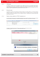
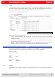
6. Operating the reader 6.1.2. USB header English If a RRU4 is connected to the PC via USB, the unit is installed in the system as a USB HID-compliant device. Correct logging in can be seen in the program if a reader number appears in the drop-down menu. This number is unique for each reader. If several readers are connected to the PC, the related reader can be selected on this menu. Clicking on Open now establishes the connection between the reader and PC. 6.1.3.
6. English Operating the reader The user will be informed with the status messages about the progress of the reset process. The final message will be „Reader with IP Address 192.168.0.1 …. (???????????) . Note From reader firmware 2.04, the reader in the ex-works condition has the IP address 192.168.0.1 with the network mask 255.255.255.0. Reader versions earlier than this are configured for DHCP.
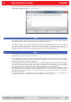
6. Operating the reader 6.1.5. I/O card configuration English The communication interface settings can be changed using the IO card configuration. All available I/O cards are displayed here in the form of tabs. Clicking on the respective tab opens the associated card and displays all respective configuration parameters, together with the card type that was detected.
6. English Operating the reader The communication parameters are grouped as follows: 1 Baud rate – the speed of the connection. All popular serial data rates up to 230,400 bps are supported 2 Data bits – the number of data bits transmitted per byte. The card supports 5 – 8 data bits. 3 Parity – a bit for security of the data transmission If None is selected, this bit is not transmitted. For all other settings this bit is transmitted.
. English Operating the reader If the LEDs are present (only for ARU), the LED channels can be assigned various functionalities under this heading. Further parameters can be activated, depending on the function selected.
6. English Operating the reader Each input channel has two configuration parameters available. The Invert logical input option negates the electrical input signal and uses this status for processing in the reader. If the check is not set, the signal is used unchanged. Depending on the sensor being used (mechanical or electrical switch), a debounce time in milliseconds can be assigned to each channel. The outputs from the card can be assigned various functions.
6. Operating the reader 6.1.5.3. RS485 English In order to establish a serial symmetrical connection to the EIA-485 standard, a RS485/RS422 card is required for the reader. In addition to the parameters Baud rate, parity and stop bits, which are identical to RS232, the tab for configuration of this interface has certain other specific settings under the Port settings header. The LED control is only possible with ARU reader.
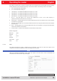
6. English Operating the reader The settings for the LED display are visible only if ARU reader. Figure: Configuration parameters for the Ethernet module The parameters have the following functions: 1 Name – Here the host name of the reader which is logged on to the DNS server is stated. The reader can be addressed by this name as an alternative to the IP address.
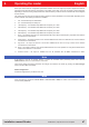
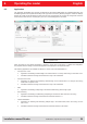
6. Operating the reader 6.2. Application English The Application tab enables quick and easy configuration of the Kathrein RFID Reader for a selected application. The available applications are represented visually in the upper area of the tab by labelled pictograms. Under the Settings header, the number of tags expected, the antennas to be used, the parameter set in which the configuration should be saved and the values for max. read frequency and max. read reliability options are stated.
6.
6. Operating the reader 6.3. Basic read functions English This index card is divided into two columns, the first column contains a table with information about the read tags, and in the second column you can find the controls, which control the reading process.
6. English Operating the reader The row "number of unique tags" specifies how many different tags were read. When the Tag count is very high (> 200) the detection of the tags can be speeded up, by commanding the reader may change to new "select command" (see EPC global standard (E)). This can be tested by selecting "Expert Parameters" directly in read mode. If the read operation box is ticked with "Transmit Select If No Filter Is On", a "Select" is sent in each "Inventory".
6. Operating the reader 6.3.2. Synchronous mode English This mode is intended for applications when the requirements for timing are not so demanding. This mode allows the facility to switch the carrier off during the idle times, thus saving power. The inventory of the tags (the read process) is performed across all the antennas that are configured. Once all tags in the field have been read on the last antenna, data are sent to the PC.
6. Operating the reader 6.4. Basic writing function English The Basic writing tab allows input of basic descriptions of tags. A fundamental distinction is maintained between synchronous writing - write on command - and asynchronous writing - write on arrival. Figure: Basic write function tab 6.4.1. Synchronous writing In this type of writing the data can only ever be written selectively to one EPC. This is selected in the EPC ComboBox.
6. Operating the reader 6.4.2. Asynchronous writing English In this type of writing the data is written to every EPC that occurs in the antenna field. When all necessary data (password, memory bank, memory address, data to be described - the input of the data mask is optional) have been input, clicking on Start starts the asynchronous write process. Successful and failed write attempts are shown in the respective fields.
6. English Operating the reader 6.5. GPIO functions Readers with GPIO functionality offer the facility to set up small controls which trigger the reader for instance by a light barrier or which trigger an action at the outputs of the reader by reading specific tags. Such an action might be switching an output to control the flow of goods. The GPIO function tab allows the user of the program the facility to load or switch inputs and outputs manually.
6. Operating the reader English Note When the action list has been created, it is assigned under the Assign input to action list header to an input and a selected flank. If it is desired to assign the list to both flanks, the assignment must be made once for the positive flank and once for the negative flank. The assignment can be cancelled again by a restart/reset of the reader or by assignment of the No action list item. The action lists that are created are stored only in the RAM of the reader.
6. Operating the reader 6.5.1. Example of GPIO function English In the same menu, the basic functions of the GPIO card can be set. First, the IO-card configuration is opened and the GPIO card set automatic detection on GPIO: Here the global settings for the GPIOs are set. Invertieren: when logically high level and high-level physica must be inverted Debounce time depending on the switching element at the entrance Output ->TAG found „antenna mistake“ ....
English 6. Operating the reader 6.5.1.4. Selecting commands from the ACTION list The commands of the Action List are now under the menu item „GPIO functions / Action List“ available at „action“ all available commands are listed. In the example, „Get EPCs“ „Add Action“ with the commands are written in chronological list of the selected action. Each command will be added in the system banner with the message „GPIOAddActionToActionlist (9): Successfully“ acknowledged.
English 6. Operating the reader 6.5.1.5. Assigning the ACTION list to the respective inputs Have been added, all of the commands to be executed, is in the menu box „way to input action list to“ bring about the link to the inputs. The action list (in this case 9) and the input (in this case 1) can be selected. Similarly, to determine whether to respond to the rising or falling edge is. By clicking the „Apply“ on the action list is associated with the input.
6. Operating the reader 6.6. Expert settings English The ReaderStart v2 software is a powerful tool for configuration of the reader. It allows the reader to be customised to any application. The expert settings 1 and 2 allow the reader's RF interface and communications profile to be optimised to the tag so that the reader is optimally customised to the application. 6.6.1. Expert settings 1 There are eight parameter sets available for saving the configuration of the reader.
6. English Operating the reader Pre-setting can be selected under the Current parameter set header. This is done by selecting a parameter set in the drop-down menu. This parameter is now active and loaded, and the headers are updated. When all the desired changes have been made, they can be saved. The changes to the settings can be discarded by pressing the Reload configuration button. The parameter set can be reloaded by pressing the Load factory defaults.
6. English Operating the reader GHW = Gisot – 2.14dB GHW....Gain based on a half-wave dipole Gisot....Gain based on an isotropic radiator in dBi If the gain of the antenna is referred to the polarisation of a circular isotropic antenna (dBic), the linear gain of the antenna is 3 dB lower. As a result the transmission power can be increased by 3 dB. GHW = Gisot – 2.14dB – 3dB GHW....Gain based on a half-wave dipole Gisot....
6. Operating the reader 6.6.1.2. Antenna multiplex configuration English The sequence in which the antennas are used to read the tag can be set under this header. If this antenna is not activated, the system proceeds to the next entry on the multiplex list. For asynchronous operation of the reader, the exposure time on the antenna can also be specified. See section ((B)) „configurational manual reader“, sections MultiplexingAntennaport and MultiplexingExposureTime for more details. 6.6.1.3.
6. Operating the reader 6.6.2. Expert settings 2 English The Expert settings 2 tab is split into four headings for further configuration of the Kathrein RRU4 reader. The default parameter set can be changed, one parameter set copied into another,reader parameters read to determine their ID and select filter settings configured.
6. Operating the reader 6.7. Test Gen2 functions English This tab makes it possible to access individual functions of the reader. This includes, along with the functionality in accordance with the EPC-Gen2 standard, e. g.: read individual tags, describe tags, set and change passwords, and also select the antenna for the operation. The user interface consists of the headers Get all EPCs, Write EPC, Change password, Read/write data, Lock, Kill and the display window for EPCs that have been read.
6. 6.7.1. English Operating the reader Get all EPCs To read a tag in this menu, the Get all EPCs button must be clicked once the reader has been correctly configured. The reader now tries once again to read all the tags in the field of the selected antenna. If in the Antenna selection drop-down menu the number of antennas has been restricted, reading will now be performed using the currently selected antenna, or using the antenna selected with All in the Expert settings 1.
6. Operating the reader 6.7.4. Read/write data English This header supplies detailed access to all the data areas of the tag. Access is obtained by entering the selected memory bank, the address within the memory bank and the number of words, expressed as 16-bit words. If data are to be written, they must be entered in the Data to write field. The data mask allows only individual bits on the tag to be changed. To do this, the mask must be entered in the Data mask field.
6. Operating the reader 6.7.6. Kill English Pressing the Kill selected tag button, with the stated password, executes a Kill command on this tag. The Kill all tags button, with the stated password, attempts to execute a Kill command on all the tag in the field. Note For the deactivation of a tag, a deactivation password that is not 0 must have been set. Note After a Kill tag command, the tag will be unusable. Installation manual Reader Modifications, misprints and errors excepted.
6. Operating the reader 6.8. © KRAI-Settings English The basic settings of the reader parameters appear in this Installation Manual Reader from Chapter 6 “Descriptions and operation of the reader” and can be set and configured through the Reader Start Software. © The KRAI-specific settings are explained in the following text. You can find this setting in the Reader Start Software section, under the tab "KRAI".
6. English Operating the reader The choice of configuration options depends on the types of the connected antennas. The category polarisation is for antennas with polarisation switching, and the cable attenuation category is available for use by SmartShelf antennas. Depending on the features that are integrated in the antennas LEDs can be controlled / configured under the section LED.
6. English Operating the reader Reading and setting the configuration is done via the buttons “Read LED Configuration” and “Set LED configuration”. The configuration change is done immediately. If the function access protocol for the LEDs is chosen, it can be adjusted in the submenu LED and residual period for the LED can be set. With buttons “Switch LED On” the LED is switched on for ms duration. The “Switch LED Off” button switches off the chosen LED.
6. Operating the reader 6.9. App Manager English The AppManager manages Linux application on the Linux part of the ELC and ETL Reader. To make this possible, each application must have the following structure: E2C4D78C-C9FE-4594-8153-82B51312166E 59E1F344-C5AE-4662-9A82-D5F265A16271 EC5BD95F-1296-4F94-957F-897219748C9C Access Manager 1.00.00.
6. English Operating the reader The ACCESS Manager is activated using the button "Start app". The signal bar in the indicator changes from red to green. A tick in the "start app at boot" target application box will resume the app set after a power failure.
6. Operating the reader 6.10.2. Reading point English On the input field "read point", the respective entrances and exits are recorded. At the same time the "read time" is set in msec. 6.10.3. Reading point - Antenna relationship The corresponding reading points are linked to the physical antennas with the "read point antenna" relationship. 6.10.4. Entrance The tab "Input" specifies the starting condition for the reading points. If e.g.
6. Operating the reader 6.10.5. Reading point – entrance relationship English With the "read point – entrance relationship" the trigger is linked to the read point. 6.10.6. Output Then, the digital outputs are allocated. This will then set which action should take place (here enable barrier = entrance open), and also which digital output is activated (output 1) and how long the switching pulse will be.
6. Operating the reader 6.10.7. User Groups English The permissions are distributed through the relationship between reading points, user groups and the outputs. Here, of course, a user group (in this case service employees) can have access to multiple reading points. 6.10.8. Read point - User Group - Output - relationship The next tab shows the allocation of read points, user groups and outputs. Please note that all authorised users groups are also listed for each read point.
6. Operating the reader 6.10.9. Tag – User Group relationship English Finally, the unique transponders are assigned to the respective representatives of the user group, so as to achieve an unambiguous classification and identification of vehicles and users. This can be either a “Name”, “Username” or “ID”. After expanding the input mask using the “>” button, the current transponder is read. This can always be re-launched via the menu item “Update”.
6. English Operating the reader After selecting „Connect“ a password is required to access. The default password is „UHF-RFID-Dev“ . Under „Options“ > „Intelligence module“ > „Secure connection config“ the settings for the SSH can be installed. The password can be changed with “Change Linux password” Installation manual Reader Modifications, misprints and errors excepted.
6. Operating the reader 6.12.
7. English Programming the Reader For the integration of the reader into an existing application on Windows, Linux for operation as a standalone device with embedded Linux appropriate libraries and header files are located on the CD in the subdirectory / API. The user has the choice to use the appropriate target system library for Windows or Linux, or to implement KBRP according to the supplied protocol specification ((A)) in its target application.
7. English Programming the Reader Note The paths in the config.mk file must match those in your build system, so that the build process can be successful. If the build process is successful, the program can be transferred to the reader. One way to transfer the data is described in Section 7.7. 7.6.
7. English Programming the Reader On the included CD/DVD is a file named “config.mk”. This file is for the compilation of programs for the reader and is incorporated in the Makefiles (include config.mk)(see example below). ELDK_SYSROOTS ELDK_TOOLCHAIN_SYSROOT ELDK_ARM_SYSROOT CROSS_COMPILE ARCHITECTURE_CFLAGS := /opt/eldk-5.
7. Programming the Reader 7.7. Installation Linux application English The reader is equipped with a separate module, running a linux on it. That gives the user the opportunity to install an application that will start automatically after powering up the reader. The flash memory is divided into a writable and a read only part of the file system. This application note describes how to install a user application to the non-volatile memory (flash) of the reader.
7. Programming the Reader English So now we have an application in the non volatile memory on the target that is allowed to be executed. The next and last step is to make it bootable by default after power up. During boot process the script inittab is called. This script looks for a script named startup in the directory /flash. The linux will execute its content on every boot. Therefore we need to add the programcall in that script.
8. English List of references „communication protocol“ ((A)) for software developers „configurational manual reader“ ((B)) for commissioning „installation manual reader“ ((C)) Setup and installation "installation manual antenna“ ((D)) Setup and installation „EPCGlobal standard“ ((E)) for software developers „Putty is SSH and Telnet-Client“ ((F)) for software developers ((E)) EPCTM Radio-Frequency Identity Protocols Class-1 Generation-2 UHF RFID in version V1.2.0 : www.epcglobalinc.
9. English contact address address contact Kathrein RFID E-Mail: rfid-sales@kathrein-rfid.de Kronstaudener Weg 1 Internet: www.kathrein-rfid.de D-83071 Stephanskirchen Installation manual Reader Modifications, misprints and errors excepted.