
Installation Manual Part 2


Installation manual Reader 46
Modications, misprints and errors excepted.
English
6. Operating the reader
6.1.5.2. GPIO
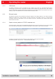
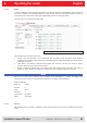
Figure: Conguration of the GPIO card
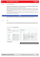
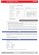
If the LEDs are present (only for ARU), the LED channels can be assigned various functionalities under this heading.
Further parameters can be activated, depending on the function selected. The following functions are available:
1 Off – the selected LED is deactivated
2 On – the selected LED is always on
3 1Hz frequency – the selected LED ashes at a frequency of 1 Hertz
4 2Hz frequency – the selected LED ashes at a frequency of 2 Hertz
5 4Hz frequency – the selected LED ashes at a frequency of 4 Hertz
6 8Hz frequency – the selected LED ashes at a frequency of 8 Hertz
7 RF on – the LED lights up for Turn-off time milliseconds as soon as the radio frequency is
present at the antenna First antenna to Last antenna.
8 Antenna error – the LED lights up for Turn-off time milliseconds as soon as an antenna error occurs at antenna
First antenna to Last antenna.
9 Tag found – the LED lights up for Turn-off time milliseconds as soon as a tag is found at the antenna First antenna
to Last antenna.
10 RF on – the LED lights up for Turn-off time milliseconds as soon as an operation on a tag was successful at the
antenna First antenna to Last antenna.
11 Protocol access – the LED can be switched on and off directly via the protocol.
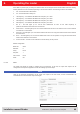
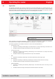
Default conguration:
Baud rate: 9600
Data bits: 8
Parity: None
Stop bits: 1
Flow control: None
LEDs: Off
The GPIO card allows the reader to interact with its environment. In this tab, the inputs and outputs can be
congured for the respective application under the headings Input and Output.
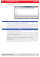
Note
Refer to the electrical characteristics of the inputs and outputs in the data sheet; if these characteristics are
exceeded the card and the reader may be damaged.