
User's Manual

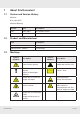
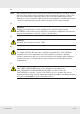

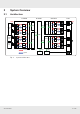
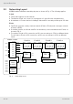
Table Of Contents
- 1 About this Document
- 2 General Information
- 3 Preconditions and Requirements
- 4 Installing the C-Hub
- 5 Installing the E-Hub
- 6 Installing the HPRU
- 7 Cabling
- 8 System Documentation
- 9 Glossary
- 10 List of Diagrams
- 11 List of Tables
- Fig. 1: Scope of delivery
- Fig. 2: Example of a handover point for the BTS signals at a c-rail
- Fig. 3: Example of a handover point for the BTS signals with individual loads with short patch cables at a c-rail
- Fig. 4: Clearance Ⓐ above radiation fins of the installed devices
- Fig. 5: Sliding rails Ⓑ
- Fig. 6: Power distribution bar ① mounted on the left-hand traverse
- Fig. 7: Plugs for power connection: ① is for red circuit, ② for black circuit
- Fig. 8: Attaching a 19" mounting bracket
- Fig. 9: Attached sliding rails Ⓑ
- Fig. 10: Place C-hub in rack
- Fig. 11: Fix C-hub with screws
- Fig. 12: Connect power cable at rear side
- Fig. 13: Connect ground cable at rear side
- Fig. 14: Attaching a 19" mounting bracket
- Fig. 15: Marking position of mounting holes
- Fig. 16: Mounting completed
- Fig. 17: Connect power cable at rear side
- Fig. 18: Connect ground cable at rear side
- Fig. 19: Attaching handle
- Fig. 20: Attaching bracket Ⓐ
- Fig. 21: Marking mounting holes for bracket Ⓑ
- Fig. 22: Prepare expansion bolts for bracket Ⓑ
- Fig. 23: Mounting accessories for bracket Ⓑ
- Fig. 24: Bracket Ⓑ mounted
- Fig. 25: Hook HPRU into bracket Ⓑ (①) and fix from top (②).
- Fig. 26: HPRU fixed from top
- Fig. 27: Fix HPRU from side
- Fig. 28: Connect power cable at bottom side
- Fig. 29: Connect ground cable at bottom side
- Fig. 30: Interfaces at the C-hub front side
- Fig. 31: Interfaces at the C-hub rear side
- Fig. 32: Interfaces at the E-hub front side
- Fig. 33: Interfaces at the E-hub rear side
- Fig. 34: Interfaces at the HPRU connector side
- Fig. 35: Fibre optical cable layout
- Fig. 36: Coaxial cable layout
- Fig. 37: Power supply cable layout
- Tab. 1: Symbols and signal words
- Tab. 2: Storage of the system documentation

10 of 20
System Overview
936.5465 0.92
3.2 Networking Layout
K-BOW enables different networking layouts as shown in Fig. 2. The following applies:
C-hub
● The C-hub supports a star network:
● The Master C-hub can connect to a maximum of 2 slave C-hubs simultaneously.
● A maximum of 5 slave devices including E-hub and RU cascade per bre port of C-hub.
E-hub
● The E-hub supports a daisy-chained network (E-hub to E-hub) and a star-type network
(E-hub to HPRU).
● In smaller systems, the C-hub and RU can be directly connected without the E-hub, as
shown in Fig. 2.
● For a direct C-hub to RU connection, an RU can cascade up to 5 RUs at different levels.
For a C-hub to E-hub to RU connection, an RU can cascade up to 4 RUs at different
levels.
Fibre
Fibre
Fibre
Fibre
Fibre
Fibre
Fibre
Fibre
Maximum 4 daisy chained RU
Slave
C-HUB 2
OP1/AU
AU1
AU2
OP1/AU
OP2
OP3
OP4
OP5
OP6
Slave
C-HUB 1
OP1/AU
B
and 5
B
and 1
B
and 2
B
and 3
B
and 4
B
and 8
B
and 7
B
and 6
B
and 9
B
and 12
B
and 11
B
and 10
slave
RF-1
RF-2
RU
master
slave
RF-1
RF-2
RU
master
slave
RF-
1
RF-
2
RU
master
masterslave
OP1
OP2
OP3
OP4
OP5
OP6
masterslave
OP1
OP2
OP3
OP4
OP5
OP6
masterslave
OP1
OP2
OP3
OP4
OP5
OP6
masterslave
OP1
OP2
OP3
OP4
OP5
OP6
Master C-HUB
E-HUB 1 E-HUB 2 E-HUB 3 E-HUB 4
Maximum 3 daisy chained RU
Fig. 2: Networking layout