
User's Manual

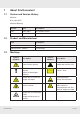
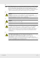

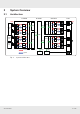
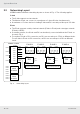
Table Of Contents
- 1 About this Document
- 2 General Information
- 3 Preconditions and Requirements
- 4 Installing the C-Hub
- 5 Installing the E-Hub
- 6 Installing the HPRU
- 7 Cabling
- 8 System Documentation
- 9 Glossary
- 10 List of Diagrams
- 11 List of Tables
- Fig. 1: Scope of delivery
- Fig. 2: Example of a handover point for the BTS signals at a c-rail
- Fig. 3: Example of a handover point for the BTS signals with individual loads with short patch cables at a c-rail
- Fig. 4: Clearance Ⓐ above radiation fins of the installed devices
- Fig. 5: Sliding rails Ⓑ
- Fig. 6: Power distribution bar ① mounted on the left-hand traverse
- Fig. 7: Plugs for power connection: ① is for red circuit, ② for black circuit
- Fig. 8: Attaching a 19" mounting bracket
- Fig. 9: Attached sliding rails Ⓑ
- Fig. 10: Place C-hub in rack
- Fig. 11: Fix C-hub with screws
- Fig. 12: Connect power cable at rear side
- Fig. 13: Connect ground cable at rear side
- Fig. 14: Attaching a 19" mounting bracket
- Fig. 15: Marking position of mounting holes
- Fig. 16: Mounting completed
- Fig. 17: Connect power cable at rear side
- Fig. 18: Connect ground cable at rear side
- Fig. 19: Attaching handle
- Fig. 20: Attaching bracket Ⓐ
- Fig. 21: Marking mounting holes for bracket Ⓑ
- Fig. 22: Prepare expansion bolts for bracket Ⓑ
- Fig. 23: Mounting accessories for bracket Ⓑ
- Fig. 24: Bracket Ⓑ mounted
- Fig. 25: Hook HPRU into bracket Ⓑ (①) and fix from top (②).
- Fig. 26: HPRU fixed from top
- Fig. 27: Fix HPRU from side
- Fig. 28: Connect power cable at bottom side
- Fig. 29: Connect ground cable at bottom side
- Fig. 30: Interfaces at the C-hub front side
- Fig. 31: Interfaces at the C-hub rear side
- Fig. 32: Interfaces at the E-hub front side
- Fig. 33: Interfaces at the E-hub rear side
- Fig. 34: Interfaces at the HPRU connector side
- Fig. 35: Fibre optical cable layout
- Fig. 36: Coaxial cable layout
- Fig. 37: Power supply cable layout
- Tab. 1: Symbols and signal words
- Tab. 2: Storage of the system documentation

7 of 20936.5465 0.92
(3)
Note
Only authorized person can enter the area where the antenna is installed. Andthe
person is fully aware of the potential for exposure and can exercise control over
his or her exposure by leaving the area or by some other appropriate means.
Awareness of the potential for RFexposure in a workplace or similar environment
can be provided through speci c training as part of a RFsafety program
(4)
Warning
Changes or modi cations to this equipment not expressly approved by
KATHREIN could void the user’s authority to operate the equipment. At least two
persons are required to carry 19"racks to avoid injuries.
(5)
Warning
Antenna gain should not exceed 7dBi.
(6)
Warning
To comply with FCC RFexposure compliance requirements, each individual
antenna used for this transmitter must be installed to provide a separation
distance greater than 205cm or more from all persons during normal operation
and must not be co-located with any other antenna for meeting RFexposure
requirements.
(7)
Warning
This is NOT a CONSUMER device. It is designed for installation by
FCCLICENSEES and QUALIFIED INSTALLERS. You MUST have an
FCCLICENSE or express consent of an FCCLicense to operate this device.
Unauthorized use may result in signi cant forfeiture penalties, including penalties
in excess of $100,000 for each continuing violation.