
User's Manual


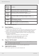


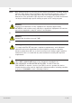


Table Of Contents
- 1 About this Document
- 2 General Information
- 3 Preconditions and Requirements
- 4 Installing the C-Hub
- 5 Installing the E-Hub
- 6 Installing the HPRU
- 7 Cabling
- 8 System Documentation
- 9 Glossary
- 10 List of Diagrams
- 11 List of Tables
- Fig. 1: Scope of delivery
- Fig. 2: Example of a handover point for the BTS signals at a c-rail
- Fig. 3: Example of a handover point for the BTS signals with individual loads with short patch cables at a c-rail
- Fig. 4: Clearance Ⓐ above radiation fins of the installed devices
- Fig. 5: Sliding rails Ⓑ
- Fig. 6: Power distribution bar ① mounted on the left-hand traverse
- Fig. 7: Plugs for power connection: ① is for red circuit, ② for black circuit
- Fig. 8: Attaching a 19" mounting bracket
- Fig. 9: Attached sliding rails Ⓑ
- Fig. 10: Place C-hub in rack
- Fig. 11: Fix C-hub with screws
- Fig. 12: Connect power cable at rear side
- Fig. 13: Connect ground cable at rear side
- Fig. 14: Attaching a 19" mounting bracket
- Fig. 15: Marking position of mounting holes
- Fig. 16: Mounting completed
- Fig. 17: Connect power cable at rear side
- Fig. 18: Connect ground cable at rear side
- Fig. 19: Attaching handle
- Fig. 20: Attaching bracket Ⓐ
- Fig. 21: Marking mounting holes for bracket Ⓑ
- Fig. 22: Prepare expansion bolts for bracket Ⓑ
- Fig. 23: Mounting accessories for bracket Ⓑ
- Fig. 24: Bracket Ⓑ mounted
- Fig. 25: Hook HPRU into bracket Ⓑ (①) and fix from top (②).
- Fig. 26: HPRU fixed from top
- Fig. 27: Fix HPRU from side
- Fig. 28: Connect power cable at bottom side
- Fig. 29: Connect ground cable at bottom side
- Fig. 30: Interfaces at the C-hub front side
- Fig. 31: Interfaces at the C-hub rear side
- Fig. 32: Interfaces at the E-hub front side
- Fig. 33: Interfaces at the E-hub rear side
- Fig. 34: Interfaces at the HPRU connector side
- Fig. 35: Fibre optical cable layout
- Fig. 36: Coaxial cable layout
- Fig. 37: Power supply cable layout
- Tab. 1: Symbols and signal words
- Tab. 2: Storage of the system documentation

8 of 20
General Information
936.5465 0.92
2.3 Intended Use
The K-BOW system is a micro C-RAN solution to provide exible and ef ciently scalable
coverage and capacity for multi-operator and multi-band scenarios using a common
infrastructure. The system offers mobile radio single routing capabilities to support exible
sectoring for network load balancing as well as individual signal power optimization of
remote RF unit level. The system use cases are the following:
●
Operating K-BOW as a repeater by
– interfacing cable based RFsignals from base stations to the C-hub,
–
relaying the radio signal of the base stations into at least one or multiple radio cells via
remote units with antennas connected to these using coaxial cables,
●
Routing base station signals
●
Supporting MIMO operation on selected bands