
Datasheet
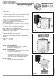


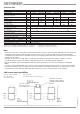


Type EXR 308 EXR 334 VWS 330
Order Nr. 273348 273349 230599
Frequency range MHz 47–862 950–2400 47–862 950–2400 47–862 950–2400
Inputs/Outputs/ 3 / - / 8 3 / 3 / 4 3 / 3 / -
Subscriber connections
Through loss dB – – 3 3 – –
Tap loss dB 9 10 17 13 – –
Gain dB – – – – 13 11
max. output level dBµV 85
1
)85
2
)– 85
2
) 110
1
) 110
2
)
(3rd order prod.)
max. operation level dBµV – – – – 105
3
)98
4
)
Current drain from power unit mA 150 40 120
Current drain from receiver mA 1 20 –
each subscriber
max. current drain form DC connection mA 150 – 300
(not short-circuit proof)
Type / Order Nr. NCF 18 / 230636
nominal input voltage V~ 230 (50–60 Hz)
admissible input voltage range V~ 198–253
secondary voltage V= 18 ± 5%
Current drain mA max. 650
Consumption W typ. 14,5
Safety class/Protection category II (Safety insulation)/IP 30
935.1841/C/0805/2.4e
Technical data
1
) 60 dB X. mod. / 3 transmitter measurement method B acc. to DIN 450043
3
) distributing 6 TV channels and FM signals.
2
) 35 dB I. mod./ 2 transmitter measurement method acc. to EN 50083-3
4
) distributing 32 TV channels each polarisation.
Note
– Systems for more than 4 subscribers need be planned with at least one switching matrix EXR 308 (a power supply unit
for remote power feeding to LNBs and the matrices is in the scope of delivery of EXR 308. The matrix is generally
installewd as the final matrix in a distribution system. A through-line matrix EXR 334 is needed for system extension to
another four subscribers.
Example: 16 receivers = 1 x EXR 308 + 2 x EXR 334- Depending on the signal level and the cable loss, it will be
possible to feed the signals to 16 receivers without having to use a Sat matrix amplifier VWS 330.
– Not needed outputs have to be terminated with the resistor type EMK 03 to assure electromagnetic compatibility
(EMC).
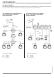
– If a matrix system amplifier VWS 330 is used in a system, the LNB and the switching matrices in front of the amplifier
receive the operating power from the power unit of the amplifier. The amplifier and the post-circuited matrices can be
powered either via the switching matrix EXR 308 or via the second DC connection point on the amplifier.
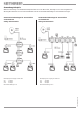
LNB current supply possibilities
650 – 150 = 500 mA for LNB 650 mA for LNB
max. 200 mA from max. 300 mA from 14 V connection point
14 V connection point
When calculating the totally required supply voltages, the current drain of all active components in the system must be taken into account.
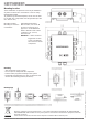
Connection point for
LNB supply voltage or
pre-circuited matrices
Alternative connection
point for power supply to
amplifier or matrices from
NCF 18